|
công cụ tìm kiếm bảng dữ liệu linh kiện điện tử |
|
|
công cụ tìm kiếm bảng dữ liệu linh kiện điện tử |
|
PIC16F1516 bảng dữ liệu(PDF) 176 Page - Microchip Technology |
|
|
|||||||||||||||||||||||||||||
PIC16F1516 bảng dữ liệu(HTML) 176 Page - Microchip Technology |
|
|
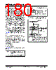
176 / 344 page  PIC16(L)F1516/7/8/9 DS41452B-page 176 Preliminary 2011 Microchip Technology Inc. 20.1 Capture Mode The Capture mode function described in this section is available and identical for all CCP modules. Capture mode makes use of the 16-bit Timer1 resource. When an event occurs on the CCPx pin, the 16-bit CCPRxH:CCPRxL register pair captures and stores the 16-bit value of the TMR1H:TMR1L register pair, respectively. An event is defined as one of the following and is configured by the CCPxM<3:0> bits of the CCPxCON register: • Every falling edge • Every rising edge • Every 4th rising edge • Every 16th rising edge When a capture is made, the Interrupt Request Flag bit CCPxIF of the PIRx register is set. The interrupt flag must be cleared in software. If another capture occurs before the value in the CCPRxH, CCPRxL register pair is read, the old captured value is overwritten by the new captured value. Figure 20-1 shows a simplified diagram of the Capture operation. 20.1.1 CCP PIN CONFIGURATION In Capture mode, the CCPx pin should be configured as an input by setting the associated TRIS control bit. Also, the CCP2 pin function can be moved to alternative pins using the APFCON register. Refer to Section Register 12-1: “APFCON: Alternate Pin Function Control Register” for more details. FIGURE 20-1: CAPTURE MODE OPERATION BLOCK DIAGRAM 20.1.2 TIMER1 MODE RESOURCE Timer1 must be running in Timer mode or Synchronized Counter mode for the CCP module to use the capture feature. In Asynchronous Counter mode, the capture operation may not work. See Section 18.0 “Timer1 Module with Gate Control” for more information on configuring Timer1. 20.1.3 SOFTWARE INTERRUPT MODE When the Capture mode is changed, a false capture interrupt may be generated. The user should keep the CCPxIE interrupt enable bit of the PIEx register clear to avoid false interrupts. Additionally, the user should clear the CCPxIF interrupt flag bit of the PIRx register following any change in Operating mode. 20.1.4 CCP PRESCALER There are four prescaler settings specified by the CCPxM<3:0> bits of the CCPxCON register. Whenever the CCP module is turned off, or the CCP module is not in Capture mode, the prescaler counter is cleared. Any Reset will clear the prescaler counter. Switching from one capture prescaler to another does not clear the prescaler and may generate a false interrupt. To avoid this unexpected operation, turn the module off by clearing the CCPxCON register before changing the prescaler. Equation 20-1 demonstrates the code to perform this function. EXAMPLE 20-1: CHANGING BETWEEN CAPTURE PRESCALERS Note: If the CCPx pin is configured as an output, a write to the port can cause a capture condition. CCPRxH CCPRxL TMR1H TMR1L Set Flag bit CCPxIF (PIRx register) Capture Enable CCPxM<3:0> Prescaler 1, 4, 16 and Edge Detect pin CCPx System Clock (FOSC) BANKSEL CCPxCON ;Set Bank bits to point ;to CCPxCON CLRF CCPxCON ;Turn CCP module off MOVLW NEW_CAPT_PS ;Load the W reg with ;the new prescaler ;move value and CCP ON MOVWF CCPxCON ;Load CCPxCON with this ;value |
|
Link URL |
| Cho đến nay ALLDATASHEET có giúp ích cho doanh nghiệp của bạn hay không? [ DONATE ] |
Alldatasheet là | Quảng cáo | Liên lạc với chúng tôi | Chính sách bảo mật | Liên kết đến bảng dữ liệu | Trao đổi link | Tìm kiếm theo nhà sản xuất All Rights Reserved©Alldatasheet.com |
| Russian : Alldatasheetru.com | Korean : Alldatasheet.co.kr | Spanish : Alldatasheet.es | French : Alldatasheet.fr | Italian : Alldatasheetit.com Portuguese : Alldatasheetpt.com | Polish : Alldatasheet.pl | Vietnamese : Alldatasheet.vn Indian : Alldatasheet.in | Mexican : Alldatasheet.com.mx | British : Alldatasheet.co.uk | New Zealand : Alldatasheet.co.nz |
|
Family Site : ic2ic.com |
icmetro.com |
 Vietnamese ▼
 English
 Chinese
 German
 Japanese
 Russian
 Korean
 Spanish
 French
 Italian
 Portuguese
 Polish
 Vietnamese
 Indian
 Mexican
 British
 New Zealand