|
công cụ tìm kiếm bảng dữ liệu linh kiện điện tử |
|
|
công cụ tìm kiếm bảng dữ liệu linh kiện điện tử |
|
PIC16F1516 bảng dữ liệu(PDF) 62 Page - Microchip Technology |
|
|
|||||||||||||||||||||||||||||
PIC16F1516 bảng dữ liệu(HTML) 62 Page - Microchip Technology |
|
|
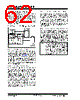
62 / 344 page  PIC16(L)F1516/7/8/9 DS41452B-page 62 Preliminary 2011 Microchip Technology Inc. 5.5 Fail-Safe Clock Monitor The Fail-Safe Clock Monitor (FSCM) allows the device to continue operating should the external oscillator fail. The FSCM can detect oscillator failure any time after the Oscillator Start-up Timer (OST) has expired. The FSCM is enabled by setting the FCMEN bit in the Configuration Word 1. The FSCM is applicable to all external Oscillator modes (LP, XT, HS, EC, RC and secondary oscillator). FIGURE 5-9: FSCM BLOCK DIAGRAM 5.5.1 FAIL-SAFE DETECTION The FSCM module detects a failed oscillator by comparing the external oscillator to the FSCM sample clock. The sample clock is generated by dividing the LFINTOSC by 64. See Figure 5-9. Inside the fail detector block is a latch. The external clock sets the latch on each falling edge of the external clock. The sample clock clears the latch on each rising edge of the sample clock. A failure is detected when an entire half-cycle of the sample clock elapses before the external clock goes low. 5.5.2 FAIL-SAFE OPERATION When the external clock fails, the FSCM switches the device clock to an internal clock source and sets the bit flag OSFIF of the PIR2 register. Setting this flag will generate an interrupt if the OSFIE bit of the PIE2 register is also set. The device firmware can then take steps to mitigate the problems that may arise from a failed clock. The system clock will continue to be sourced from the internal clock source until the device firmware successfully restarts the external oscillator and switches back to external operation. The internal clock source chosen by the FSCM is determined by the IRCF<3:0> bits of the OSCCON register. This allows the internal oscillator to be configured before a failure occurs. 5.5.3 FAIL-SAFE CONDITION CLEARING The Fail-Safe condition is cleared after a Reset, executing a SLEEP instruction or changing the SCS bits of the OSCCON register. When the SCS bits are changed, the OST is restarted. While the OST is running, the device continues to operate from the INTOSC selected in OSCCON. When the OST times out, the Fail-Safe condition is cleared and the device will be operating from the external clock source. The Fail-Safe condition must be cleared before the OSFIF flag can be cleared. 5.5.4 RESET OR WAKE-UP FROM SLEEP The FSCM is designed to detect an oscillator failure after the Oscillator Start-up Timer (OST) has expired. The OST is used after waking up from Sleep and after any type of Reset. The OST is not used with the EC or RC Clock modes so that the FSCM will be active as soon as the Reset or wake-up has completed. When the FSCM is enabled, the Two-Speed Start-up is also enabled. Therefore, the device will always be executing code while the OST is operating. External LFINTOSC ÷ 64 S R Q 31 kHz (~32 s) 488 Hz (~2 ms) Clock Monitor Latch Clock Failure Detected Oscillator Clock Q Sample Clock Note: Due to the wide range of oscillator start-up times, the Fail-Safe circuit is not active during oscillator start-up (i.e., after exiting Reset or Sleep). After an appropriate amount of time, the user should check the Status bits in the OSCSTAT register to verify the oscillator start-up and that the system clock switchover has successfully completed. |
|
Link URL |
| Cho đến nay ALLDATASHEET có giúp ích cho doanh nghiệp của bạn hay không? [ DONATE ] |
Alldatasheet là | Quảng cáo | Liên lạc với chúng tôi | Chính sách bảo mật | Liên kết đến bảng dữ liệu | Trao đổi link | Tìm kiếm theo nhà sản xuất All Rights Reserved©Alldatasheet.com |
| Russian : Alldatasheetru.com | Korean : Alldatasheet.co.kr | Spanish : Alldatasheet.es | French : Alldatasheet.fr | Italian : Alldatasheetit.com Portuguese : Alldatasheetpt.com | Polish : Alldatasheet.pl | Vietnamese : Alldatasheet.vn Indian : Alldatasheet.in | Mexican : Alldatasheet.com.mx | British : Alldatasheet.co.uk | New Zealand : Alldatasheet.co.nz |
|
Family Site : ic2ic.com |
icmetro.com |
 Vietnamese ▼
 English
 Chinese
 German
 Japanese
 Russian
 Korean
 Spanish
 French
 Italian
 Portuguese
 Polish
 Vietnamese
 Indian
 Mexican
 British
 New Zealand