|
công cụ tìm kiếm bảng dữ liệu linh kiện điện tử |
|
|
công cụ tìm kiếm bảng dữ liệu linh kiện điện tử |
|
PIC16F1516 bảng dữ liệu(PDF) 111 Page - Microchip Technology |
|
|
|||||||||||||||||||||||||||||
PIC16F1516 bảng dữ liệu(HTML) 111 Page - Microchip Technology |
|
|
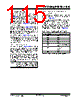
111 / 344 page  2011 Microchip Technology Inc. Preliminary DS41452B-page 111 PIC16(L)F1516/7/8/9 REGISTER 11-5: PMCON1: PROGRAM MEMORY CONTROL 1 REGISTER U-1(1) R/W-0/0 R/W-0/0 R/W/HC-0/0 R/W/HC-x/q(2) R/W-0/0 R/S/HC-0/0 R/S/HC-0/0 — CFGS LWLO FREE WRERR WREN WR RD bit 7 bit 0 Legend: R = Readable bit W = Writable bit U = Unimplemented bit, read as ‘0’ S = Bit can only be set x = Bit is unknown -n/n = Value at POR and BOR/Value at all other Resets ‘1’ = Bit is set ‘0’ = Bit is cleared HC = Bit is cleared by hardware bit 7 Unimplemented: Read as ‘1’ bit 6 CFGS: Configuration Select bit 1 = Access Configuration, User ID and Device ID Registers 0 = Access Flash program memory bit 5 LWLO: Load Write Latches Only bit(3) 1 = Only the addressed program memory write latch is loaded/updated on the next WR command 0 = The addressed program memory write latch is loaded/updated and a write of all program memory write latches will be initiated on the next WR command bit 4 FREE: Program Flash Erase Enable bit 1 = Performs an erase operation on the next WR command (hardware cleared upon completion) 0 = Performs an write operation on the next WR command bit 3 WRERR: Program/Erase Error Flag bit 1 = Condition indicates an improper program or erase sequence attempt or termination (bit is set automatically on any set attempt (write ‘1’) of the WR bit). 0 = The program or erase operation completed normally. bit 2 WREN: Program/Erase Enable bit 1 = Allows program/erase cycles 0 = Inhibits programming/erasing of program Flash bit 1 WR: Write Control bit 1 = Initiates a program Flash program/erase operation. The operation is self-timed and the bit is cleared by hardware once operation is complete. The WR bit can only be set (not cleared) in software. 0 = Program/erase operation to the Flash is complete and inactive. bit 0 RD: Read Control bit 1 = Initiates a program Flash read. Read takes one cycle. RD is cleared in hardware. The RD bit can only be set (not cleared) in software. 0 = Does not initiate a program Flash read. Note 1: Unimplemented bit, read as ‘1’. 2: The WRERR bit is automatically set by hardware when a program memory write or erase operation is started (WR = 1) . 3: The LWLO bit is ignored during a program memory erase operation (FREE = 1). |
|
Link URL |
| Cho đến nay ALLDATASHEET có giúp ích cho doanh nghiệp của bạn hay không? [ DONATE ] |
Alldatasheet là | Quảng cáo | Liên lạc với chúng tôi | Chính sách bảo mật | Liên kết đến bảng dữ liệu | Trao đổi link | Tìm kiếm theo nhà sản xuất All Rights Reserved©Alldatasheet.com |
| Russian : Alldatasheetru.com | Korean : Alldatasheet.co.kr | Spanish : Alldatasheet.es | French : Alldatasheet.fr | Italian : Alldatasheetit.com Portuguese : Alldatasheetpt.com | Polish : Alldatasheet.pl | Vietnamese : Alldatasheet.vn Indian : Alldatasheet.in | Mexican : Alldatasheet.com.mx | British : Alldatasheet.co.uk | New Zealand : Alldatasheet.co.nz |
|
Family Site : ic2ic.com |
icmetro.com |
 Vietnamese ▼
 English
 Chinese
 German
 Japanese
 Russian
 Korean
 Spanish
 French
 Italian
 Portuguese
 Polish
 Vietnamese
 Indian
 Mexican
 British
 New Zealand