|
công cụ tìm kiếm bảng dữ liệu linh kiện điện tử |
|
|
công cụ tìm kiếm bảng dữ liệu linh kiện điện tử |
|
PIC16F1516 bảng dữ liệu(PDF) 232 Page - Microchip Technology |
|
|
|||||||||||||||||||||||||||||
PIC16F1516 bảng dữ liệu(HTML) 232 Page - Microchip Technology |
|
|
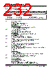
232 / 344 page  PIC16(L)F1516/7/8/9 DS41452B-page 232 Preliminary 2011 Microchip Technology Inc. 21.8 MSSP Control Registers REGISTER 21-1: SSPSTAT: SSP STATUS REGISTER R/W-0/0 R/W-0/0 R-0/0 R-0/0 R-0/0 R-0/0 R-0/0 R-0/0 SMP CKE D/A PS R/W UA BF bit 7 bit 0 Legend: R = Readable bit W = Writable bit U = Unimplemented bit, read as ‘0’ u = Bit is unchanged x = Bit is unknown -n/n = Value at POR and BOR/Value at all other Resets ‘1’ = Bit is set ‘0’ = Bit is cleared bit 7 SMP: SPI Data Input Sample bit SPI Master mode: 1 = Input data sampled at end of data output time 0 = Input data sampled at middle of data output time SPI Slave mode: SMP must be cleared when SPI is used in Slave mode In I2C Master or Slave mode: 1 = Slew rate control disabled for standard speed mode (100 kHz and 1 MHz) 0 = Slew rate control enabled for high speed mode (400 kHz) bit 6 CKE: SPI Clock Edge Select bit (SPI mode only) In SPI Master or Slave mode: 1 = Transmit occurs on transition from active to Idle clock state 0 = Transmit occurs on transition from Idle to active clock state In I2C™ mode only: 1 = Enable input logic so that thresholds are compliant with SMbus specification 0 = Disable SMbus specific inputs bit 5 D/A: Data/Address bit (I2C mode only) 1 = Indicates that the last byte received or transmitted was data 0 = Indicates that the last byte received or transmitted was address bit 4 P: Stop bit (I2C mode only. This bit is cleared when the MSSP module is disabled, SSPEN is cleared.) 1 = Indicates that a Stop bit has been detected last (this bit is ‘0’ on Reset) 0 = Stop bit was not detected last bit 3 S: Start bit (I2C mode only. This bit is cleared when the MSSP module is disabled, SSPEN is cleared.) 1 = Indicates that a Start bit has been detected last (this bit is ‘0’ on Reset) 0 = Start bit was not detected last bit 2 R/W: Read/Write bit information (I2C mode only) This bit holds the R/W bit information following the last address match. This bit is only valid from the address match to the next Start bit, Stop bit, or not ACK bit. In I2C Slave mode: 1 = Read 0 =Write In I2C Master mode: 1 = Transmit is in progress 0 = Transmit is not in progress OR-ing this bit with SEN, RSEN, PEN, RCEN or ACKEN will indicate if the MSSP is in Idle mode. bit 1 UA: Update Address bit (10-bit I2C mode only) 1 = Indicates that the user needs to update the address in the SSPADD register 0 = Address does not need to be updated bit 0 BF: Buffer Full Status bit Receive (SPI and I2C modes): 1 = Receive complete, SSPBUF is full 0 = Receive not complete, SSPBUF is empty Transmit (I2C mode only): 1 = Data transmit in progress (does not include the ACK and Stop bits), SSPBUF is full 0 = Data transmit complete (does not include the ACK and Stop bits), SSPBUF is empty |
|
Link URL |
| Cho đến nay ALLDATASHEET có giúp ích cho doanh nghiệp của bạn hay không? [ DONATE ] |
Alldatasheet là | Quảng cáo | Liên lạc với chúng tôi | Chính sách bảo mật | Liên kết đến bảng dữ liệu | Trao đổi link | Tìm kiếm theo nhà sản xuất All Rights Reserved©Alldatasheet.com |
| Russian : Alldatasheetru.com | Korean : Alldatasheet.co.kr | Spanish : Alldatasheet.es | French : Alldatasheet.fr | Italian : Alldatasheetit.com Portuguese : Alldatasheetpt.com | Polish : Alldatasheet.pl | Vietnamese : Alldatasheet.vn Indian : Alldatasheet.in | Mexican : Alldatasheet.com.mx | British : Alldatasheet.co.uk | New Zealand : Alldatasheet.co.nz |
|
Family Site : ic2ic.com |
icmetro.com |
 Vietnamese ▼
 English
 Chinese
 German
 Japanese
 Russian
 Korean
 Spanish
 French
 Italian
 Portuguese
 Polish
 Vietnamese
 Indian
 Mexican
 British
 New Zealand