|
công cụ tìm kiếm bảng dữ liệu linh kiện điện tử |
|
|
công cụ tìm kiếm bảng dữ liệu linh kiện điện tử |
|
PIC16F1516 bảng dữ liệu(PDF) 300 Page - Microchip Technology |
|
|
|||||||||||||||||||||||||||||
PIC16F1516 bảng dữ liệu(HTML) 300 Page - Microchip Technology |
|
|
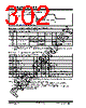
300 / 344 page  PIC16(L)F1516/7/8/9 DS41452B-page 300 Preliminary 2011 Microchip Technology Inc. TABLE 25-4: RESET, WATCHDOG TIMER, OSCILLATOR START-UP TIMER, POWER-UP TIMER AND BROWN-OUT RESET PARAMETERS Standard Operating Conditions (unless otherwise stated) Operating Temperature -40°C TA +125°C Param No. Sym. Characteristic Min. Typ† Max. Units Conditions 30 TMCLMCLR Pulse Width (low) 2 5 — — — — s s VDD = 3.3-5V, -40°C to +85°C VDD = 3.3-5V 31 TWDTLP Low-Power Watchdog Timer Time-out Period 10 16 27 ms VDD = 3.3V-5V, 1:16 Prescaler used 32 TOST Oscillator Start-up Timer Period(1), (2) — 1024 — Tosc (Note 3) 33* TPWRT Power-up Timer Period, PWRTE = 0 40 65 140 ms 34* TIOZ I/O high-impedance from MCLR Low or Watchdog Timer Reset —— 2.0 s 35 VBOR Brown-out Reset Voltage 2.38 1.80 2.5 1.9 2.65 2.05 VBORV=2.5V BORV=1.9V 36* VHYST Brown-out Reset Hysteresis 0 25 50 mV -40°C to +85°C 37* TBORDC Brown-out Reset DC Response Time 135 sVDD VBOR 38 VLPBOR Low-Power Brown-out Reset Voltage TBD TBD TBD V LPBOR = 1 * These parameters are characterized but not tested. † Data in “Typ” column is at 3.0V, 25°C unless otherwise stated. These parameters are for design guidance only and are not tested. Legend: TBD = To Be Determined Note 1: Instruction cycle period (TCY) equals four times the input oscillator time base period. All specified values are based on characterization data for that particular oscillator type under standard operating conditions with the device executing code. Exceeding these specified limits may result in an unstable oscillator operation and/or higher than expected current consumption. All devices are tested to operate at “min” values with an external clock applied to the OSC1 pin. When an external clock input is used, the “max” cycle time limit is “DC” (no clock) for all devices. 2: By design. 3: Period of the slower clock. 4: To ensure these voltage tolerances, VDD and VSS must be capacitively decoupled as close to the device as possible. 0.1 F and 0.01 F values in parallel are recommended. |
|
Link URL |
| Cho đến nay ALLDATASHEET có giúp ích cho doanh nghiệp của bạn hay không? [ DONATE ] |
Alldatasheet là | Quảng cáo | Liên lạc với chúng tôi | Chính sách bảo mật | Liên kết đến bảng dữ liệu | Trao đổi link | Tìm kiếm theo nhà sản xuất All Rights Reserved©Alldatasheet.com |
| Russian : Alldatasheetru.com | Korean : Alldatasheet.co.kr | Spanish : Alldatasheet.es | French : Alldatasheet.fr | Italian : Alldatasheetit.com Portuguese : Alldatasheetpt.com | Polish : Alldatasheet.pl | Vietnamese : Alldatasheet.vn Indian : Alldatasheet.in | Mexican : Alldatasheet.com.mx | British : Alldatasheet.co.uk | New Zealand : Alldatasheet.co.nz |
|
Family Site : ic2ic.com |
icmetro.com |
 Vietnamese ▼
 English
 Chinese
 German
 Japanese
 Russian
 Korean
 Spanish
 French
 Italian
 Portuguese
 Polish
 Vietnamese
 Indian
 Mexican
 British
 New Zealand