|
công cụ tìm kiếm bảng dữ liệu linh kiện điện tử |
|
|
công cụ tìm kiếm bảng dữ liệu linh kiện điện tử |
|
CC1110-RTY1 bảng dữ liệu(PDF) 91 Page - Texas Instruments |
|
|
|||||||||||||||||||||||||||||
CC1110-RTY1 bảng dữ liệu(HTML) 91 Page - Texas Instruments |
|
|
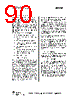
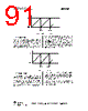
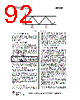
91 / 203 page  CC1110 CC1110 PRELIMINARY Datasheet (Rev. 1.01) SWRS033A Page 91 of 202 0000h FFFFh overflow overflow Figure 13: Free-running mode 13.3.4 Modulo Mode When the timer operates in modulo mode the 16-bit counter starts at 0x0000 and increments at each active clock edge. When the counter reaches the terminal count value held in registers T1CC0H:T1CC0L, the counter is reset to 0x0000 and continues to increment. The flag T1CTL.OVFIF is set when the terminal count value (overflow) is reached. An interrupt request is generated if the corresponding interrupt mask bit TIMIF.OVFIM is set. The modulo mode can be used for applications where a period other then 0xFFFF is required. The counter operation is shown in Figure 14. 0000h T1CC0 overflow overflow Figure 14: Modulo mode 13.3.5 Up/down Mode In the up/down timer mode, the counter repeatedly starts from 0x0000 and counts up until the value held in T1CC0H:T1CC0L is reached and then the counter counts down until 0x0000 is reached as shown in Figure 15. This timer mode is used when symmetrical output pulses are required with a period other than 0xFFFF, and therefore allows implementation of centre-aligned PWM output applications. The flag T1CTL.OVFIF is not set when the terminal count value is reached in the up/down mode. Clearing the counter by writing to T1CNTL will also reset the count direction to the count up from 0x0000 mode. |
|
Link URL |
| Cho đến nay ALLDATASHEET có giúp ích cho doanh nghiệp của bạn hay không? [ DONATE ] |
Alldatasheet là | Quảng cáo | Liên lạc với chúng tôi | Chính sách bảo mật | Liên kết đến bảng dữ liệu | Trao đổi link | Tìm kiếm theo nhà sản xuất All Rights Reserved©Alldatasheet.com |
| Russian : Alldatasheetru.com | Korean : Alldatasheet.co.kr | Spanish : Alldatasheet.es | French : Alldatasheet.fr | Italian : Alldatasheetit.com Portuguese : Alldatasheetpt.com | Polish : Alldatasheet.pl | Vietnamese : Alldatasheet.vn Indian : Alldatasheet.in | Mexican : Alldatasheet.com.mx | British : Alldatasheet.co.uk | New Zealand : Alldatasheet.co.nz |
|
Family Site : ic2ic.com |
icmetro.com |
 Vietnamese ▼
 English
 Chinese
 German
 Japanese
 Russian
 Korean
 Spanish
 French
 Italian
 Portuguese
 Polish
 Vietnamese
 Indian
 Mexican
 British
 New Zealand