|
công cụ tìm kiếm bảng dữ liệu linh kiện điện tử |
|
|
công cụ tìm kiếm bảng dữ liệu linh kiện điện tử |
|
ADF4252BCPZ-R7 bảng dữ liệu(PDF) 28 Page - Analog Devices |
|
|
|||||||||||||||||||||||||||||
ADF4252BCPZ-R7 bảng dữ liệu(HTML) 28 Page - Analog Devices |
|
|
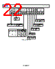
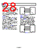
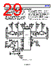
28 / 30 page  ADF4252 Data Sheet Rev. E | Page 28 of 30 INTERFACING The ADF4252 has a simple SPI-compatible serial interface for writing to the device. SCLK, SDATA, and LE control the data transfer. When LE (latch enable) goes high, the 24 bits that were clocked into the input register on each rising edge of SCLK are transferred to the appropriate latch. See Figure 2 for the timing diagram and Table 5 for the control bit truth table. The maximum allowable serial clock rate is 20 MHz, which means that the maximum update rate possible for the device is 833 kHz or one update every 1.2 μs. This is more than adequate for systems that have typical lock times in hundreds of microseconds. ADuC812 INTERFACE Figure 42 shows the interface between the ADF4252 and the ADuC812 microconverter. Because the ADuC812 is based on an 8051 core, this interface can be used with any 8051-based microcontroller. The microconverter is set up for SPI master mode with CPHA = 0. To initiate the operation, the input/output port driving LE is brought low. Each latch of the ADF4252 needs (at most) a 24-bit word. This is accomplished by writing three 8-bit bytes from the microconverter to the device. When the third byte has been written, the LE input must be brought high to complete the transfer. The input/output port lines on the ADuC812 are also used to control power-down (CE input) and to detect lock (MUXOUT configured as lock detect and polled by the port input). When operating in the mode described, the maximum SCLOCK rate of the ADuC812 is 4 MHz. This means that the maximum rate at which the output frequency can be changed is 166 kHz. ADuC812 ADF4252 SCLK SDATA LE CE MUXOUT (LOCK DETECT) SCLOCK MOSI I/O PORTS Figure 42. ADuC812 to ADF4252 Interface ADSP-2181 INTERFACE Figure 43 shows the interface between the ADF4252 and the ADSP-2181 digital signal processor. Each latch of the ADF4252 needs (at most) a 24-bit word. The easiest way to accomplish this using the ADSP-2181 is to use the autobuffered transmit mode of operation with alternate framing. This provides a means for transmitting an entire block of serial data before an interrupt is generated. Set up the word length for eight bits and use three memory locations for each 24-bit word. To program each 24-bit latch, store the three 8-bit bytes, enable the autobuffered mode, and then write to the transmit register of the DSP. This last operation initiates the autobuffer transfer. ADSP-2181 ADF4252 SCLK SDATA LE CE MUXOUT (LOCK DETECT) SCLK DT I/O FLAGS TFS Figure 43. ADSP-2181 to ADF4252 Interface |
|
Link URL |
| Cho đến nay ALLDATASHEET có giúp ích cho doanh nghiệp của bạn hay không? [ DONATE ] |
Alldatasheet là | Quảng cáo | Liên lạc với chúng tôi | Chính sách bảo mật | Liên kết đến bảng dữ liệu | Trao đổi link | Tìm kiếm theo nhà sản xuất All Rights Reserved©Alldatasheet.com |
| Russian : Alldatasheetru.com | Korean : Alldatasheet.co.kr | Spanish : Alldatasheet.es | French : Alldatasheet.fr | Italian : Alldatasheetit.com Portuguese : Alldatasheetpt.com | Polish : Alldatasheet.pl | Vietnamese : Alldatasheet.vn Indian : Alldatasheet.in | Mexican : Alldatasheet.com.mx | British : Alldatasheet.co.uk | New Zealand : Alldatasheet.co.nz |
|
Family Site : ic2ic.com |
icmetro.com |
 Vietnamese ▼
 English
 Chinese
 German
 Japanese
 Russian
 Korean
 Spanish
 French
 Italian
 Portuguese
 Polish
 Vietnamese
 Indian
 Mexican
 British
 New Zealand