|
công cụ tìm kiếm bảng dữ liệu linh kiện điện tử |
|
|
công cụ tìm kiếm bảng dữ liệu linh kiện điện tử |
|
WM9705 bảng dữ liệu(PDF) 32 Page - Wolfson Microelectronics plc |
|
|
|||||||||||||||||||||||||||||
WM9705 bảng dữ liệu(HTML) 32 Page - Wolfson Microelectronics plc |
|
|
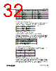
32 / 55 page  WM9705 Production Data w PD Rev 4.4 August 2006 32 SR2 TO SR0 RIGHT RECORD SOURCE SL2 TO SL0 LEFT RECORD SOURCE 0 Mic 0 Mic 1 CD in (R) 1 CD in (L) 2 Video in (R) 2 Video in (L) 3 Aux in (R) 3 Aux in (L) 4 Line in (R) 4 Line in (L) 5 Stereo mix (R) 5 Stereo mix (L) 6 Mono mix 6 Mono mix 7 Phone 7 Phone Table 11 Record Select Register Function RECORD GAIN REGISTERS (INDEX 1Ch) 1Ch sets the stereo input record gain with each step corresponding to 1.5dB. The MSB of the register is the mute bit. When this bit is set to 1, the level for both channels is set at - ∞dB. The default value is 8000h, which corresponds to 0dB gain with mute on. MUTE GX3...GX0 FUNCTION 0 1111 +22.5dB gain 0 0000 0dB gain 1 xxxxx - ∞dB gain Table 12 Record Gain Register Function GENERAL PURPOSE REGISTER (INDEX 20h) This register is used to control several miscellaneous functions of the WM9705. Below is a summary of each bit and its function. Only the POP, 3D, MIX, MS and LPBK bits are supported by the WM9705. The MS bit controls the Mic selector. The LPBK bit enables loopback of the ADC output to the DAC input without involving the AC-link, allowing for full system performance measurements. The function default value is 0000h which is all off. BIT FUNCTION POP PCM out path and mute, 0 = pre-3D, 1 = post-3D 3D 3D stereo enhancement on/off, 1 = on MIX Mono output select 0 = Mix, 1 = Mic MS Mic select 0 = Mic1, 1 = Mic2 LPBK ADC/DAC loopback mode 3D CONTROL REGISTER (INDEX 22h) This register is used to control the centre and/or depth of the 3D stereo enhancement function built into the AC’97 component. Only the depth bits DP0 to 3 have effect in the WM9705. DP3…DP0 DEPTH 0 0% 1 - 8 Typical value - 15 100% Table 13 3D Control Register POWERDOWN CONTROL/STATUS REGISTER (INDEX 26h) This read/write register is used to program power-down states and monitor subsystem readiness. The lower half of this register is read only status, a 1 indicating that the subsection is ready. Ready is defined as the subsection able to perform in its nominal state. When this register is written the bit values that come in on AC-link will have no effect on read bits 0- 7. |
|
Link URL |
| Cho đến nay ALLDATASHEET có giúp ích cho doanh nghiệp của bạn hay không? [ DONATE ] |
Alldatasheet là | Quảng cáo | Liên lạc với chúng tôi | Chính sách bảo mật | Liên kết đến bảng dữ liệu | Trao đổi link | Tìm kiếm theo nhà sản xuất All Rights Reserved©Alldatasheet.com |
| Russian : Alldatasheetru.com | Korean : Alldatasheet.co.kr | Spanish : Alldatasheet.es | French : Alldatasheet.fr | Italian : Alldatasheetit.com Portuguese : Alldatasheetpt.com | Polish : Alldatasheet.pl | Vietnamese : Alldatasheet.vn Indian : Alldatasheet.in | Mexican : Alldatasheet.com.mx | British : Alldatasheet.co.uk | New Zealand : Alldatasheet.co.nz |
|
Family Site : ic2ic.com |
icmetro.com |
 Vietnamese ▼
 English
 Chinese
 German
 Japanese
 Russian
 Korean
 Spanish
 French
 Italian
 Portuguese
 Polish
 Vietnamese
 Indian
 Mexican
 British
 New Zealand