|
công cụ tìm kiếm bảng dữ liệu linh kiện điện tử |
|
|
công cụ tìm kiếm bảng dữ liệu linh kiện điện tử |
|
ADBMS1818ASWZ-R7 bảng dữ liệu(PDF) 56 Page - Analog Devices |
|
|
|||||||||||||||||||||||||||||
ADBMS1818ASWZ-R7 bảng dữ liệu(HTML) 56 Page - Analog Devices |
|
|
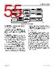
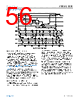
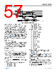
56 / 92 page  Data Sheet ADBMS1818 THEORY OF OPERATION analog.com Rev. B | 56 of 92 Figure 86. isoSPI Timing Diagram Waking Up the Serial Interface The serial ports (SPI or isoSPI) enter the low power idle state if there is no activity on Port A or Port B for a time of tIDLE. The wake-up circuit monitors activity on Pin 61 through Pin 64. If ISOMD = V–, Port A is in SPI mode. Activity on the CSB pin or SCK pin wakes up the SPI. If ISOMD = VREG, Port A is in isoSPI mode. Differential activity on IPA to IMA (or IPB to IMB) wakes up the isoSPI. The ADBMS1818 is ready to communicate when the isoSPI state changes to ready within tWAKE or tREADY, depending on the core state (see Figure 53 and the Sleep State, Standby State, REFUP State, and Measure State sections for details). Figure 87 shows the timing and the functionally equivalent circuit (only Port A shown). Common-mode signals do not wake up the serial interface. The interface is designed to wake up after receiving a large signal single-ended pulse, or a low-amplitude symmetric pulse. The differential signal (SCK(IPA) – CSB(IMA)), must be at least VWAKE = 200 mV for a minimum duration of tDWELL = 240 ns to qualify as a wake-up signal that powers up the serial interface. Waking a Daisy Chain—Method 1 The ADBMS1818 sends a long +1 pulse on Port B after it is ready to communicate. In a daisy-chained configuration, this pulse wakes up the next device in the stack which, in turn, wakes up the next device. If there are N devices in the stack, all the devices are powered up within the time N × tWAKE or N × tREADY, depending on the core state. For large stacks, the time N × tWAKE may be equal to or larger than tIDLE. In this case, after waiting longer than the time of N × tWAKE, the host can send another dummy byte and wait for the time N × tREADY to ensure that all devices are in the ready state. Method 1 can be used when all devices on the daisy chain are in the idle state, which guarantees that the devices propagate the wake-up signal up the daisy chain. However, this method fails to wake up all devices when a device in the middle of the chain is in the ready state instead of the idle state. When this happens, the device in the ready state does not propagate the wake-up pulse, so the devices above it remain in the idle state. This situation can occur when attempting to wake up the daisy chain after only tIDLE of idle time (some devices may be idle, some may not). |
|
Link URL |
| Cho đến nay ALLDATASHEET có giúp ích cho doanh nghiệp của bạn hay không? [ DONATE ] |
Alldatasheet là | Quảng cáo | Liên lạc với chúng tôi | Chính sách bảo mật | Liên kết đến bảng dữ liệu | Trao đổi link | Tìm kiếm theo nhà sản xuất All Rights Reserved©Alldatasheet.com |
| Russian : Alldatasheetru.com | Korean : Alldatasheet.co.kr | Spanish : Alldatasheet.es | French : Alldatasheet.fr | Italian : Alldatasheetit.com Portuguese : Alldatasheetpt.com | Polish : Alldatasheet.pl | Vietnamese : Alldatasheet.vn Indian : Alldatasheet.in | Mexican : Alldatasheet.com.mx | British : Alldatasheet.co.uk | New Zealand : Alldatasheet.co.nz |
|
Family Site : ic2ic.com |
icmetro.com |
 Vietnamese ▼
 English
 Chinese
 German
 Japanese
 Russian
 Korean
 Spanish
 French
 Italian
 Portuguese
 Polish
 Vietnamese
 Indian
 Mexican
 British
 New Zealand