|
công cụ tìm kiếm bảng dữ liệu linh kiện điện tử |
|
|
công cụ tìm kiếm bảng dữ liệu linh kiện điện tử |
|
ADBMS1818ASWZ-R7 bảng dữ liệu(PDF) 11 Page - Analog Devices |
|
|
|||||||||||||||||||||||||||||
ADBMS1818ASWZ-R7 bảng dữ liệu(HTML) 11 Page - Analog Devices |
|
|
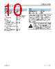
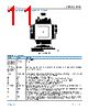
11 / 89 page  Data Sheet ADBMS1818 PIN CONFIGURATION AND FUNCTION DESCRIPTIONS analog.com Rev. 0 | 11 of 89 Figure 3. Pin Configuration Table 12. Pin Function Descriptions Pin No. Mnemonic Description 1 V+ Positive Supply Pin. 2, 4, 6, 8, 10, 12, 14, 16, 18, 20, 22, 24, 26, 28, 30, 32, 34, 36, 38 C0 to C18 Cell Inputs. 3, 5, 7, 9, 11, 13, 15, 17, 19, 21, 23, 25, 27, 29, 31, 33, 35, 37 S1 to S18 Balance Inputs/Outputs. 18 internal N-channel metal-oxide semiconductor field effect transistors (MOSFETs) are connected between S(n) and C(n–1) for discharging cells. 39 to 47 GPIO1 to GPIO9 General Purpose I/O. GPIO1 to GPIO9 can be used as digital inputs or digital outputs or as analog inputs with a measurement range from V– to 5 V. GPIO3, GPIO4, and GPIO5 can be used as I2C or SPI ports. 48 VREG 5 V Regulator Input. Bypass with an external 1 μF capacitor. 49 DRIVE Connect the base of an NPN transistor to the DRIVE pin. Connect the collector to V+ and the emitter to VREG. 50 VREF2 Buffered 2nd Reference Voltage for Driving Multiple 10 kΩ Thermistors. Bypass with an external 1 μF capacitor. 51 VREF1 ADC Reference Voltage. Bypass with an external 1 μF capacitor. No dc loads allowed. 52 DTEN Discharge Timer Enable. Connect DTEN to VREG to enable the discharge timer. 53, 54, 61, 62 SDI, SDO, CSB, SCK 4-Wire SPI. Active low chip select (CSB), serial clock (SCK), and serial data in (SDI) are digital inputs. Serial data out (SDO) is an open drain NMOS output pin. SDO requires a 5 kΩ pull-up resistor. 55 ISOMD Serial Interface Mode. Connecting ISOMD to VREG configures Pin 53, Pin 54, Pin 61, and Pin 62 of the ADBMS1818 for 2-wire isoSPI mode. Connecting ISOMD to V– configures the ADBMS1818 for 4-wire SPI mode. 56 WDT Watchdog Timer Output Pin. This is an open drain negative metal-oxide semiconductor (NMOS) digital output. WDT can be left disconnected or connected with a 1 M resistor to VREG. If the ADBMS1818 does not receive a valid command within 2 seconds, the watchdog timer circuit resets the ADBMS1818 and the WDT pin goes high impedance. 57 IBIAS Isolated Interface Current Bias. Tie IBIAS to V– through a resistor divider to set the interface output current level. When the isoSPI interface is enabled, the IBIAS pin voltage is 2 V. The IPA and IMA or IPB and IMB output current drive is set to 20 times the current, IB, sourced from the IBIAS pin. |
|
Link URL |
| Cho đến nay ALLDATASHEET có giúp ích cho doanh nghiệp của bạn hay không? [ DONATE ] |
Alldatasheet là | Quảng cáo | Liên lạc với chúng tôi | Chính sách bảo mật | Liên kết đến bảng dữ liệu | Trao đổi link | Tìm kiếm theo nhà sản xuất All Rights Reserved©Alldatasheet.com |
| Russian : Alldatasheetru.com | Korean : Alldatasheet.co.kr | Spanish : Alldatasheet.es | French : Alldatasheet.fr | Italian : Alldatasheetit.com Portuguese : Alldatasheetpt.com | Polish : Alldatasheet.pl | Vietnamese : Alldatasheet.vn Indian : Alldatasheet.in | Mexican : Alldatasheet.com.mx | British : Alldatasheet.co.uk | New Zealand : Alldatasheet.co.nz |
|
Family Site : ic2ic.com |
icmetro.com |
 Vietnamese ▼
 English
 Chinese
 German
 Japanese
 Russian
 Korean
 Spanish
 French
 Italian
 Portuguese
 Polish
 Vietnamese
 Indian
 Mexican
 British
 New Zealand