|
công cụ tìm kiếm bảng dữ liệu linh kiện điện tử |
|
|
công cụ tìm kiếm bảng dữ liệu linh kiện điện tử |
|
ADBMS1818ASWZ-R7 bảng dữ liệu(PDF) 53 Page - Analog Devices |
|
|
|||||||||||||||||||||||||||||
ADBMS1818ASWZ-R7 bảng dữ liệu(HTML) 53 Page - Analog Devices |
|
|
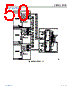
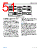
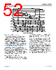
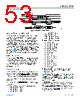
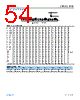
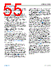
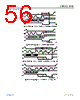
53 / 89 page  Data Sheet ADBMS1818 THEORY OF OPERATION analog.com Rev. 0 | 53 of 89 Figure 87. Wake-Up Detection and Idle Timer Waking a Daisy Chain—Method 2 A more robust wake-up method does not rely on the built-in wake- up pulse, but manually sends isoSPI traffic for enough time to wake the entire daisy chain. At a minimum, a pair of long isoSPI pulses (–1 and +1) is needed for each device, separated by more than tREADY or tWAKE (if the core state is standby mode or sleep mode, respectively), but less than tIDLE. This allows each device to wake up and propagate the next pulse to the following device. This method works even if some devices in the chain are not in the idle state. In practice, implementing Method 2 requires toggling the CSB pin (of the LTC6820, or bottom ADBMS1818 with ISOMD = 0) to generate the long isoSPI pulses. Alternatively, dummy commands (such as RDCFGA) can be executed to generate the long isoSPI pulses. DATA LINK LAYER All data transfers on ADBMS1818 occur in byte groups. Every byte consists of 8 bits. Bytes are transferred with the MSB first. CSB must remain low for the entire duration of a command sequence, including between a command byte and subsequent data. On a write command, data is latched in on the rising edge of CSB. NETWORK LAYER Packet Error Code The PEC is a 15-bit cyclic redundancy check (CRC) value calculat- ed for all of the bits in a register group in the order they are passed, using the initial PEC value of 000000000010000 and the following characteristic polynomial: x15 + x14 + x10 + x8 + x7 + x4 + x3 + 1. To calculate the 15-bit PEC value, a simple procedure can be established: 1. Initialize the PEC to 000000000010000 (PEC is a 15‑bit register group). 2. For each bit DIN coming into the PEC register group, set: ► IN0 = DIN XOR PEC, Bit 14 ► IN3 = IN0 XOR PEC, Bit 2 ► IN4 = IN0 XOR PEC, Bit 3 ► IN7 = IN0 XOR PEC, Bit 6 ► IN8 = IN0 XOR PEC, Bit 7 ► IN10 = IN0 XOR PEC, Bit 9 ► IN14 = IN0 XOR PEC, Bit 13 3. Update the 15-bit PEC as follows: ► PEC, Bit 14 = IN14 ► PEC, Bit 13 = PEC, Bit 12 ► PEC, Bit 12 = PEC, Bit 11 ► PEC, Bit 11 = PEC, Bit 10 ► PEC, Bit 10 = IN10 ► PEC, Bit 9 = PEC, Bit 8 ► PEC, Bit 8 = IN8 ► PEC, Bit 7 = IN7 ► PEC, Bit 6 = PEC, Bit 5 ► PEC, Bit 5 = PEC, Bit 4 ► PEC, Bit 4 = IN4 ► PEC, Bit 3 = IN3 ► PEC, Bit 2 = PEC, Bit 1 ► PEC, Bit 1 = PEC, Bit 0 ► PEC, Bit 0 = IN0 4. Go back to Step 2 until all the data is shifted. The final PEC (16 bits) is the 15-bit value in the PEC register with a 0 bit appended to its LSB. Figure 88 shows the 15-bit PEC algorithm. An example to calculate the PEC for a 16-bit word (0x0001) is listed in Table 43. The PEC for 0x0001 is computed as 0x3D6E after stuffing a 0 bit at the LSB. For longer data streams, the PEC is valid at the end of the last bit of data sent to the PEC register. The ADBMS1818 calculates the PEC for any command or data received and compares it with the PEC following the command or data. The command or data is regarded as valid only if the PEC matches. ADBMS1818 also attaches the calculated PEC at the end of the data it shifts out. Table 44 shows the format of PEC while writing to or reading from ADBMS1818. |
|
Link URL |
| Cho đến nay ALLDATASHEET có giúp ích cho doanh nghiệp của bạn hay không? [ DONATE ] |
Alldatasheet là | Quảng cáo | Liên lạc với chúng tôi | Chính sách bảo mật | Liên kết đến bảng dữ liệu | Trao đổi link | Tìm kiếm theo nhà sản xuất All Rights Reserved©Alldatasheet.com |
| Russian : Alldatasheetru.com | Korean : Alldatasheet.co.kr | Spanish : Alldatasheet.es | French : Alldatasheet.fr | Italian : Alldatasheetit.com Portuguese : Alldatasheetpt.com | Polish : Alldatasheet.pl | Vietnamese : Alldatasheet.vn Indian : Alldatasheet.in | Mexican : Alldatasheet.com.mx | British : Alldatasheet.co.uk | New Zealand : Alldatasheet.co.nz |
|
Family Site : ic2ic.com |
icmetro.com |
 Vietnamese ▼
 English
 Chinese
 German
 Japanese
 Russian
 Korean
 Spanish
 French
 Italian
 Portuguese
 Polish
 Vietnamese
 Indian
 Mexican
 British
 New Zealand