|
công cụ tìm kiếm bảng dữ liệu linh kiện điện tử |
|
|
công cụ tìm kiếm bảng dữ liệu linh kiện điện tử |
|
ADBMS1818ASWZ-R7 bảng dữ liệu(PDF) 78 Page - Analog Devices |
|
|
|||||||||||||||||||||||||||||
ADBMS1818ASWZ-R7 bảng dữ liệu(HTML) 78 Page - Analog Devices |
|
|
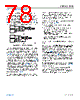
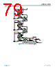
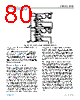
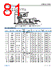
78 / 89 page  Data Sheet ADBMS1818 APPLICATIONS INFORMATION analog.com Rev. 0 | 78 of 89 Implementing a Modular isoSPI Daisy Chain The hardware design of a daisy-chain isoSPI bus is identical for each device in the network due to the daisy-chain point to point architecture. The simple design as shown in Figure 103 is function- al, but inadequate for most designs. The termination resistor, RM, must be split and bypassed with a capacitor, as shown in Figure 104. This change provides both a differential and a common mode termination, and as such, increases the system noise immunity. Figure 104. Daisy Chain Interface Components The use of cables between battery modules, particularly in hazard applications, can lead to increased noise susceptibility in the com- munication lines. For high levels of electromagnetic interference (EMC), additional filtering is recommended. The circuit example in Figure 104 shows the use of common-mode chokes (CMC) to add common-mode noise rejection from transients on the battery lines. The use of a center tapped transformer also provides additional noise performance. A bypass capacitor connected to the center tap creates a low impedance for common-mode noise (see Figure 104). Since transformers without a center tap can be less expensive, they may be preferred. In this case, the addition of a split termination resistor and a bypass capacitor (see Figure 104) can enhance the isoSPI performance. Large center tap capacitors greater than 10 nF must be avoided as they may prevent the isoSPI common-mode voltage from settling. Common-mode chokes similar to those used in Ethernet or CANbus applications are recommended. Specific examples are provided in Table 73. An important daisy chain design consideration is the number of devices in the isoSPI network. The length of the chain determines the serial timing and affects data latency and throughput. The maximum number of devices in an isoSPI daisy chain is strictly dictated by the serial timing requirements. However, it is important to note that the serial read back time, and the increased current consumption, might dictate a practical limitation. For a daisy chain, the following two timing considerations for proper operation dominate (see Figure 86): 1. t6, the time between the last clock and the rising chip select, must be long enough. 2. t5, the time from a rising chip select to the next falling chip select (between commands), must be long enough. Both t5 and t6 must be lengthened as the number of ADBMS1818 devices in the daisy chain increases. The equa- tions for these times are below: t5 > (Number of Devices × 70 ns) + 900 ns, t6 > (Number of Devices × 70 ns) + 950 ns Connecting Multiple ADBMS1818s on the Same PCB When connecting multiple ADBMS1818 devices on the same PCB, only a single transformer is required between the ADBMS1818 isoSPI ports. The absence of the cable also reduces the noise levels on the communication lines and often only a split termination is required. Figure 105 shows an example application that has multiple ADBMS1818 devices on the same PCB, communicating to the bottom MCU through an LTC6820 isoSPI driver. If a transformer with a center tap is used, a capacitor can be added for improved noise rejection. Additional noise filtering can be provided with dis- crete common-mode chokes (not shown) placed on both sides of the single transformer. On single board designs with low noise requirements, it is possible for a simplified capacitor isolated coupling as shown in Figure 106 to replace the transformer. In this circuit, the transformer is directly replaced by two 10 nF capacitors. An optional CMC provides noise rejection similar to application circuits using transformers. The circuit is designed to use IBIAS and ICMP settings identical to the transformer circuit. |
|
Link URL |
| Cho đến nay ALLDATASHEET có giúp ích cho doanh nghiệp của bạn hay không? [ DONATE ] |
Alldatasheet là | Quảng cáo | Liên lạc với chúng tôi | Chính sách bảo mật | Liên kết đến bảng dữ liệu | Trao đổi link | Tìm kiếm theo nhà sản xuất All Rights Reserved©Alldatasheet.com |
| Russian : Alldatasheetru.com | Korean : Alldatasheet.co.kr | Spanish : Alldatasheet.es | French : Alldatasheet.fr | Italian : Alldatasheetit.com Portuguese : Alldatasheetpt.com | Polish : Alldatasheet.pl | Vietnamese : Alldatasheet.vn Indian : Alldatasheet.in | Mexican : Alldatasheet.com.mx | British : Alldatasheet.co.uk | New Zealand : Alldatasheet.co.nz |
|
Family Site : ic2ic.com |
icmetro.com |
 Vietnamese ▼
 English
 Chinese
 German
 Japanese
 Russian
 Korean
 Spanish
 French
 Italian
 Portuguese
 Polish
 Vietnamese
 Indian
 Mexican
 British
 New Zealand