|
công cụ tìm kiếm bảng dữ liệu linh kiện điện tử |
|
|
công cụ tìm kiếm bảng dữ liệu linh kiện điện tử |
|
DCS-7316XFM-R bảng dữ liệu(PDF) 21 Page - Arista Networks, Inc |
|
|
|||||||||||||||||||||||||||||
DCS-7316XFM-R bảng dữ liệu(HTML) 21 Page - Arista Networks, Inc |
|
|
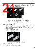
21 / 66 page  Rack Mounting the Switch Rack posts and guide pins that insert into the rack are visible from the outer side of the ear (Inset B). To install ears into posts with threaded or round holes, remove both plugs from each ear (if required for rail set), then install the ears with screws that fit the rack. Figure 8: Mounting Ears 1 Brace (Inner view) 4 Inset A - Released 7 Inset B (Details) 2 Inset A 5 Brace (Outer view) 8 Rack plugs 3 Inset A - Locked 6 Inset B 3.2.2 Component Placement Figure 9: Component Placement displays component placement for a 7304 (8-RU) switch. Mounting ears brace the top of the switch; their rack placement position differs for each switch model. Using the placement of the shelves’ bottom front rack plug as a reference (first RU and first hole), the mounting ears are placed as follows: • 7304: 8th RU (22nd through 24th holes) • 7308: 13th RU (37th through 39th holes) • 7316: 21st RU (61st through 63rd holes) Figure 9: Component Placement 3.2.3 Switch Mounting Process The switch mounting process consists of three steps: 17 |
|
Link URL |
| Cho đến nay ALLDATASHEET có giúp ích cho doanh nghiệp của bạn hay không? [ DONATE ] |
Alldatasheet là | Quảng cáo | Liên lạc với chúng tôi | Chính sách bảo mật | Liên kết đến bảng dữ liệu | Trao đổi link | Tìm kiếm theo nhà sản xuất All Rights Reserved©Alldatasheet.com |
| Russian : Alldatasheetru.com | Korean : Alldatasheet.co.kr | Spanish : Alldatasheet.es | French : Alldatasheet.fr | Italian : Alldatasheetit.com Portuguese : Alldatasheetpt.com | Polish : Alldatasheet.pl | Vietnamese : Alldatasheet.vn Indian : Alldatasheet.in | Mexican : Alldatasheet.com.mx | British : Alldatasheet.co.uk | New Zealand : Alldatasheet.co.nz |
|
Family Site : ic2ic.com |
icmetro.com |
 Vietnamese ▼
 English
 Chinese
 German
 Japanese
 Russian
 Korean
 Spanish
 French
 Italian
 Portuguese
 Polish
 Vietnamese
 Indian
 Mexican
 British
 New Zealand