|
công cụ tìm kiếm bảng dữ liệu linh kiện điện tử |
|
|
công cụ tìm kiếm bảng dữ liệu linh kiện điện tử |
|
ASP00886IRGCT bảng dữ liệu(PDF) 29 Page - Texas Instruments |
|
|
|
|||||||||||||||||||||||||||||
ASP00886IRGCT bảng dữ liệu(HTML) 29 Page - Texas Instruments |
|
|
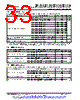
29 / 128 page  MSP430F5529, MSP430F5528, MSP430F5527, MSP430F5526 MSP430F5525, MSP430F5524, MSP430F5522, MSP430F5521 MSP430F5519, MSP430F5517, MSP430F5515, MSP430F5514, MSP430F5513 www.ti.com SLAS590M – MARCH 2009 – REVISED NOVEMBER 2015 5.16 Crystal Oscillator, XT2 over recommended ranges of supply voltage and operating free-air temperature (unless otherwise noted) (1) (2) PARAMETER TEST CONDITIONS VCC MIN TYP MAX UNIT fOSC = 4 MHz, XT2OFF = 0, XT2BYPASS = 0, 200 XT2DRIVEx = 0, TA = 25°C fOSC = 12 MHz, XT2OFF = 0, XT2BYPASS = 0, 260 XT2DRIVEx = 1, TA = 25°C XT2 oscillator crystal IDVCC.XT2 3.0 V µA current consumption fOSC = 20 MHz, XT2OFF = 0, XT2BYPASS = 0, 325 XT2DRIVEx = 2, TA = 25°C fOSC = 32 MHz, XT2OFF = 0, XT2BYPASS = 0, 450 XT2DRIVEx = 3, TA = 25°C XT2 oscillator crystal fXT2,HF0 XT2DRIVEx = 0, XT2BYPASS = 0(3) 4 8 MHz frequency, mode 0 XT2 oscillator crystal fXT2,HF1 XT2DRIVEx = 1, XT2BYPASS = 0 (3) 8 16 MHz frequency, mode 1 XT2 oscillator crystal fXT2,HF2 XT2DRIVEx = 2, XT2BYPASS = 0 (3) 16 24 MHz frequency, mode 2 XT2 oscillator crystal fXT2,HF3 XT2DRIVEx = 3, XT2BYPASS = 0 (3) 24 32 MHz frequency, mode 3 XT2 oscillator logic-level fXT2,HF,SW square-wave input XT2BYPASS = 1(4) (3) 0.7 32 MHz frequency, bypass mode XT2DRIVEx = 0, XT2BYPASS = 0, 450 fXT2,HF0 = 6 MHz, CL,eff = 15 pF XT2DRIVEx = 1, XT2BYPASS = 0, 320 fXT2,HF1 = 12 MHz, CL,eff = 15 pF Oscillation allowance for OAHF Ω HF crystals(5) XT2DRIVEx = 2, XT2BYPASS = 0, 200 fXT2,HF2 = 20 MHz, CL,eff = 15 pF XT2DRIVEx = 3, XT2BYPASS = 0, 200 fXT2,HF3 = 32 MHz, CL,eff = 15 pF fOSC = 6 MHz, XT2BYPASS = 0, XT2DRIVEx = 0, 0.5 TA = 25°C, CL,eff = 15 pF tSTART,HF Start-up time 3.0 V ms fOSC = 20 MHz, XT2BYPASS = 0, XT2DRIVEx = 2, 0.3 TA = 25°C, CL,eff = 15 pF Integrated effective load CL,eff capacitance, HF 1 pF mode(6)(1) Duty cycle Measured at ACLK, fXT2,HF2 = 20 MHz 40% 50% 60% Oscillator fault fFault,HF XT2BYPASS = 1(8) 30 300 kHz frequency(7) (1) Requires external capacitors at both terminals. Values are specified by crystal manufacturers. In general, an effective load capacitance of up to 18 pF can be supported. (2) To improve EMI on the XT2 oscillator the following guidelines should be observed. • Keep the traces between the device and the crystal as short as possible. • Design a good ground plane around the oscillator pins. • Prevent crosstalk from other clock or data lines into oscillator pins XT2IN and XT2OUT. • Avoid running PCB traces underneath or adjacent to the XT2IN and XT2OUT pins. • Use assembly materials and processes that avoid any parasitic load on the oscillator XT2IN and XT2OUT pins. • If conformal coating is used, ensure that it does not induce capacitive or resistive leakage between the oscillator pins. (3) This represents the maximum frequency that can be input to the device externally. Maximum frequency achievable on the device operation is based on the frequencies present on ACLK, MCLK, and SMCLK cannot be exceed for a given range of operation. (4) When XT2BYPASS is set, the XT2 circuit is automatically powered down. Input signal is a digital square wave with parametrics defined in the Schmitt-trigger Inputs section of this data sheet. (5) Oscillation allowance is based on a safety factor of 5 for recommended crystals. (6) Includes parasitic bond and package capacitance (approximately 2 pF per pin). Because the PCB adds additional capacitance, TI recommends verifying the correct load by measuring the ACLK frequency. For a correct setup, the effective load capacitance should always match the specification of the used crystal. (7) Frequencies below the MIN specification set the fault flag. Frequencies above the MAX specification do not set the fault flag. Frequencies between the MIN and MAX specifications might set the flag. (8) Measured with logic-level input frequency but also applies to operation with crystals. Copyright © 2009–2015, Texas Instruments Incorporated Specifications 29 Submit Documentation Feedback Product Folder Links: MSP430F5529 MSP430F5528 MSP430F5527 MSP430F5526 MSP430F5525 MSP430F5524 MSP430F5522 MSP430F5521 MSP430F5519 MSP430F5517 MSP430F5515 MSP430F5514 MSP430F5513 |
|
Link URL |
| Cho đến nay ALLDATASHEET có giúp ích cho doanh nghiệp của bạn hay không? [ DONATE ] |
Alldatasheet là | Quảng cáo | Liên lạc với chúng tôi | Chính sách bảo mật | Liên kết đến bảng dữ liệu | Trao đổi link | Tìm kiếm theo nhà sản xuất All Rights Reserved©Alldatasheet.com |
| Russian : Alldatasheetru.com | Korean : Alldatasheet.co.kr | Spanish : Alldatasheet.es | French : Alldatasheet.fr | Italian : Alldatasheetit.com Portuguese : Alldatasheetpt.com | Polish : Alldatasheet.pl | Vietnamese : Alldatasheet.vn Indian : Alldatasheet.in | Mexican : Alldatasheet.com.mx | British : Alldatasheet.co.uk | New Zealand : Alldatasheet.co.nz |
|
Family Site : ic2ic.com |
icmetro.com |
 Vietnamese ▼
 English
 Chinese
 German
 Japanese
 Russian
 Korean
 Spanish
 French
 Italian
 Portuguese
 Polish
 Vietnamese
 Indian
 Mexican
 British
 New Zealand