|
công cụ tìm kiếm bảng dữ liệu linh kiện điện tử |
|
|
công cụ tìm kiếm bảng dữ liệu linh kiện điện tử |
|
TMS320C31PQL60 bảng dữ liệu(PDF) 44 Page - Texas Instruments |
|
|
|||||||||||||||||||||||||||||
TMS320C31PQL60 bảng dữ liệu(HTML) 44 Page - Texas Instruments |
|
|
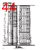
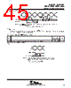
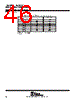
44 / 48 page  timer pin timing Valid logic-level periods and polarity are specified by the contents of the internal control registers. The following tables define the timing parameters for the timer pin. The numbers shown in Figure 31 correspond with those in the NO. column of the tables below. timing parameters for timer pin for TMS320LC31-33 (see Figure 31) † NO. DESCRIPTION‡ ’LC31-33 ’C31-40, ’LC31-40 UNIT MIN MAX MIN MAX 88 tsu(TCLK-H1L) Setup time, TCLK external before H1 low 12 10 ns 89 th(H1L-TCLK) Hold time, TCLK external after H1 low 0 0 ns 90 td(H1H-TCLK) Delay time, H1 high to TCLK internal valid 10 9 ns 91 t (TCLK) Cycle time TCLK TCLK ext tc(H)×2.6 tc(H)×2.6 ns 91 tc(TCLK) Cycle time, TCLK TCLK int tc(H)×2 tc(H)×232‡ tc(H)×2 tc(H)×232‡ ns 92 t (TCLK) Pulse duration TCLK high/low TCLK ext tc(H)+12 tc(H)+10 ns 92 tw(TCLK) Pulse duration, TCLK high/low TCLK int [tc(TCLK)/2]–15 [tc(TCLK)/2]+5 [tc(TCLK)/2]–5 [tc(TCLK)/2]+5 ns † Timing parameters 88 and 89 are applicable for a synchronous input clock. Timing parameters 91 and 92 are applicable for an asynchronous input clock. ‡ Specified by design but not tested timing parameters for timer pin for TMS320LC31-40, TMS320C31-50, and TMS320C31-60 (see Figure 31) † NO DESCRIPTION‡ ’C31-50 ’C31-60 ’C31-80 UNIT NO. DESCRIPTION‡ MIN MAX MIN MAX MIN MAX UNIT 88 tsu(TCLK-H1L) Setup time, TCLK external before H1 low 8 6 5 ns 89 th(H1L-TCLK) Hold time, TCLK external after H1 low 0 0 0 ns 90 td(H1H-TCLK) Delay time, H1 high to TCLK internal valid 9 8 6 ns 91 t (TCLK) TCLK ext tc(H)×2.6 tc(H)×2.6 tc(H)×2.6 ns 91 tc(TCLK) TCLK int tc(H)×2 tc(H)×232‡ tc(H)×2 tc(H)×232‡ tc(H)×2 tc(H)×232‡ ns 92 t (TCLK) TCLK ext tc(H)+10 tc(H)+10 tc(H)+6 ns 92 tw(TCLK) TCLK int [tc(TCLK)/2]–5 [tc(TCLK)/2]+5 [tc(TCLK)/2]–5 [tc(TCLK)/2]+5 [tc(TCLK)/2]–5 [tc(TCLK)/2]+5 ns † Timing parameters 88 and 89 are applicable for a synchronous input clock. Timing parameters 91 and 92 are applicable for an asynchronous input clock. ‡ Specified by design but not tested |
|
Link URL |
| Cho đến nay ALLDATASHEET có giúp ích cho doanh nghiệp của bạn hay không? [ DONATE ] |
Alldatasheet là | Quảng cáo | Liên lạc với chúng tôi | Chính sách bảo mật | Liên kết đến bảng dữ liệu | Trao đổi link | Tìm kiếm theo nhà sản xuất All Rights Reserved©Alldatasheet.com |
| Russian : Alldatasheetru.com | Korean : Alldatasheet.co.kr | Spanish : Alldatasheet.es | French : Alldatasheet.fr | Italian : Alldatasheetit.com Portuguese : Alldatasheetpt.com | Polish : Alldatasheet.pl | Vietnamese : Alldatasheet.vn Indian : Alldatasheet.in | Mexican : Alldatasheet.com.mx | British : Alldatasheet.co.uk | New Zealand : Alldatasheet.co.nz |
|
Family Site : ic2ic.com |
icmetro.com |
 Vietnamese ▼
 English
 Chinese
 German
 Japanese
 Russian
 Korean
 Spanish
 French
 Italian
 Portuguese
 Polish
 Vietnamese
 Indian
 Mexican
 British
 New Zealand