|
công cụ tìm kiếm bảng dữ liệu linh kiện điện tử |
|
|
công cụ tìm kiếm bảng dữ liệu linh kiện điện tử |
|
IR3553 bảng dữ liệu(PDF) 19 Page - International Rectifier |
|
|
|||||||||||||||||||||||||||||
IR3553 bảng dữ liệu(HTML) 19 Page - International Rectifier |
|
|
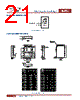
19 / 22 page  July 16, 2014 | DATASHEET V3.3 19 IR3553 40A Integrated PowIRstage® SOLDER RESIST The solder resist should be pulled away from the metal lead lands by a minimum of 0.06mm. The solder resist miss-alignment is a maximum of 0.05mm and it is recommended that the low power signal lead lands are all Non Solder Mask Defined (NSMD). Therefore pulling the S/R 0.06mm will always ensure NSMD pads. The minimum solder resist width is 0.13mm typical. At the inside corner of the solder resist where the lead land groups meet, it is recommended to provide a fillet so a solder resist width of ≥ 0.17mm remains. The dimensions of power land pads, VIN, PGND, TGND and SW, are Non Solder Mask Defined (NSMD). The equivalent PCB layout becomes Solder Mask Defined (SMD) after power shape routing. Ensure that the solder resist in-between the lead lands and the pad land is ≥ 0.15mm due to the high aspect ratio of the solder resist strip separating the lead lands from the pad land. Figure 34: Solder resist * Contact International Rectifier to receive an electronic PCB Library file in Cadence Allegro or CAD DXF/DWG format. |
|
|
Link URL |
| Cho đến nay ALLDATASHEET có giúp ích cho doanh nghiệp của bạn hay không? [ DONATE ] |
Alldatasheet là | Quảng cáo | Liên lạc với chúng tôi | Chính sách bảo mật | Liên kết đến bảng dữ liệu | Trao đổi link | Tìm kiếm theo nhà sản xuất All Rights Reserved©Alldatasheet.com |
| Russian : Alldatasheetru.com | Korean : Alldatasheet.co.kr | Spanish : Alldatasheet.es | French : Alldatasheet.fr | Italian : Alldatasheetit.com Portuguese : Alldatasheetpt.com | Polish : Alldatasheet.pl | Vietnamese : Alldatasheet.vn Indian : Alldatasheet.in | Mexican : Alldatasheet.com.mx | British : Alldatasheet.co.uk | New Zealand : Alldatasheet.co.nz |
|
Family Site : ic2ic.com |
icmetro.com |
 Vietnamese ▼
 English
 Chinese
 German
 Japanese
 Russian
 Korean
 Spanish
 French
 Italian
 Portuguese
 Polish
 Vietnamese
 Indian
 Mexican
 British
 New Zealand