|
công cụ tìm kiếm bảng dữ liệu linh kiện điện tử |
|
|
công cụ tìm kiếm bảng dữ liệu linh kiện điện tử |
|
AN753 bảng dữ liệu(PDF) 8 Page - Maxim Integrated Products |
|
|
|||||||||||||||||||||||||||||
AN753 bảng dữ liệu(HTML) 8 Page - Maxim Integrated Products |
|
|
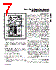
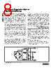
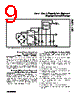
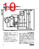
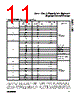
8 / 24 page  ture errors. The piezoresistive sensor is powered by a current source resulting in a temperature-dependent bridge voltage due to the sensor's temperature resis- tance coefficient (TCR). The reference inputs of the off- set TC DAC and FSOTC DAC are connected to the bridge voltage. The DAC output voltages will track the bridge voltage as it varies with temperature, and by varying the offset TC and FSOTC digital code a portion of the bridge voltage, which is temperature dependent, is used to compensate the first order temperature errors. The internal feedback resistors (RISRC and RSTC) for FSO temperature compensation are optimized to 75k Ω for silicon piezoresistive sensors. However, since the required feedback resistor values are sensor depen- dent, external resistors may also be used. The internal resistors selection bit in the configuration register selects between internal and external feedback resis- tors. To calculate the required offset TC and FSOTC com- pensation coefficients, two test-temperatures are need- ed. After taking at least two measurements at each temperature, calibration software (in a host computer) calculates the correction coefficients and writes them to the internal EEPROM. With coefficients ranging from 0000hex to FFFFhex and a +5V reference, each DAC has a resolution of 76µV. Two of the DACs (offset TC and FSOTC) utilize the sen- sor bridge voltage as a reference. Since the sensor bridge voltage is approximately set to +2.5V the FSOTC and offset TC exhibit a step size of less than 38µV. For high accuracy applications (errors less than 0.25%), the first-order offset and FSOTC should be compensated with the offset TC and FSOTC DACs, and the residual higher order terms with the lookup table. The offset and FSO compensation DACs provide unique compensation values for approximately 1.5°C of temperature change as the temperature indexes the address pointer through the coefficient lookup table. Changing the offset does not effect the FSO, however changing the FSO will affect the offset due to nature of the bridge. The temperature is measured on both the MAX1452 die and at the bridge sensor. It is recom- mended to compensate the first-order temperature errors using the bridge sensor temperature. Typical Ratiometric Operating Circuit Ratiometric output configuration provides an output that is proportional to the power supply voltage. This output can then be applied to a ratiometric ADC to produce a digital value independent of supply voltage. Ratiometricity is an important consideration for battery- operated instruments, automotive, and some industrial applications. The MAX1452 provides a high-performance ratiometric output with a minimum number of external components (Figure 2). These external components include the fol- lowing: • One supply bypass capacitor. • One optional output EMI suppression capacitor. • Two optional resistors, RISRC and RSTC, for special sensor bridge types. Low-Cost Precision Sensor Signal Conditioner 8 _______________________________________________________________________________________ Figure 2. Basic Ratiometric Output Configuration MAX1452 +5V VDD OUT GND RSTC RISRC 0.1 µF 0.1µF INM TEST VSS INP 7 9 2 16 1 8 3 BDR VDDF OUT 5 6 4 FSOTC ISRC SENSOR VDD |
|
|
Link URL |
| Cho đến nay ALLDATASHEET có giúp ích cho doanh nghiệp của bạn hay không? [ DONATE ] |
Alldatasheet là | Quảng cáo | Liên lạc với chúng tôi | Chính sách bảo mật | Liên kết đến bảng dữ liệu | Trao đổi link | Tìm kiếm theo nhà sản xuất All Rights Reserved©Alldatasheet.com |
| Russian : Alldatasheetru.com | Korean : Alldatasheet.co.kr | Spanish : Alldatasheet.es | French : Alldatasheet.fr | Italian : Alldatasheetit.com Portuguese : Alldatasheetpt.com | Polish : Alldatasheet.pl | Vietnamese : Alldatasheet.vn Indian : Alldatasheet.in | Mexican : Alldatasheet.com.mx | British : Alldatasheet.co.uk | New Zealand : Alldatasheet.co.nz |
|
Family Site : ic2ic.com |
icmetro.com |
 Vietnamese ▼
 English
 Chinese
 German
 Japanese
 Russian
 Korean
 Spanish
 French
 Italian
 Portuguese
 Polish
 Vietnamese
 Indian
 Mexican
 British
 New Zealand