|
công cụ tìm kiếm bảng dữ liệu linh kiện điện tử |
|
|
công cụ tìm kiếm bảng dữ liệu linh kiện điện tử |
|
PIC18F4680ISPQTP bảng dữ liệu(PDF) 263 Page - Microchip Technology |
|
|
|||||||||||||||||||||||||||||
PIC18F4680ISPQTP bảng dữ liệu(HTML) 263 Page - Microchip Technology |
|
|
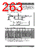
263 / 482 page  © 2007 Microchip Technology Inc. Preliminary DS39625C-page 261 PIC18F2585/2680/4585/4680 20.9 Analog Input Connection Considerations A simplified circuit for an analog input is shown in Figure 20-4. Since the analog pins are connected to a digital output, they have reverse biased diodes to VDD and VSS. The analog input, therefore, must be between VSS and VDD. If the input voltage deviates from this range by more than 0.6V in either direction, one of the diodes is forward biased and a latch-up condition may occur. A maximum source impedance of 10 k Ω is recommended for the analog sources. Any external component connected to an analog input pin, such as a capacitor or a Zener diode, should have very little leakage current. FIGURE 20-4: COMPARATOR ANALOG INPUT MODEL TABLE 20-1: REGISTERS ASSOCIATED WITH COMPARATOR MODULE VA RS < 10k AIN CPIN 5 pF VDD VT = 0.6V VT = 0.6V RIC ILEAKAGE ±500 nA VSS Legend: CPIN = Input Capacitance VT = Threshold Voltage ILEAKAGE = Leakage Current at the pin due to various junctions RIC = Interconnect Resistance RS = Source Impedance VA = Analog Voltage Comparator Input Name Bit 7 Bit 6 Bit 5 Bit 4 Bit 3 Bit 2 Bit 1 Bit 0 Reset Values on page CMCON(3) C2OUT C1OUT C2INV C1INV CIS CM2 CM1 CM0 51 CVRCON(3) CVREN CVROE CVRR CVRSS CVR3 CVR2 CVR1 CVR0 51 INTCON GIE/GIEH PEIE/GIEL TMR0IE INT0IE RBIE TMR0IF INT0IF RBIF 52 IPR2 OSCFIP CMIP(2) — EEIP BCLIP HLVDIP TMR3IP ECCP1IP(2) 51 PIR2 OSCFIF CMIF(2) — EEIF BCLIF HLVDIF TMR3IF ECCP1IF(2) 51 PIE2 OSCFIE CMIE(2) — EEIE BCLIE HLVDIE TMR3IE ECCP1IE(2) 52 PORTA RA7(1) RA6(1) RA5 RA4 RA3 RA2 RA1 RA0 52 LATA LATA7(1) LATA6(1) LATA Data Output Register 52 TRISA TRISA7(1) TRISA6(1) PORTA Data Direction Register 52 Legend: — = unimplemented, read as ‘0’. Shaded cells are unused by the comparator module. Note 1: PORTA pins are enabled based on oscillator configuration. 2: These bits are available in PIC18F4X8X devices and reserved in PIC18F2X8X devices. 3: These registers are unimplemented on PIC18F2X8X devices. |
|
Link URL |
| Cho đến nay ALLDATASHEET có giúp ích cho doanh nghiệp của bạn hay không? [ DONATE ] |
Alldatasheet là | Quảng cáo | Liên lạc với chúng tôi | Chính sách bảo mật | Liên kết đến bảng dữ liệu | Trao đổi link | Tìm kiếm theo nhà sản xuất All Rights Reserved©Alldatasheet.com |
| Russian : Alldatasheetru.com | Korean : Alldatasheet.co.kr | Spanish : Alldatasheet.es | French : Alldatasheet.fr | Italian : Alldatasheetit.com Portuguese : Alldatasheetpt.com | Polish : Alldatasheet.pl | Vietnamese : Alldatasheet.vn Indian : Alldatasheet.in | Mexican : Alldatasheet.com.mx | British : Alldatasheet.co.uk | New Zealand : Alldatasheet.co.nz |
|
Family Site : ic2ic.com |
icmetro.com |
 Vietnamese ▼
 English
 Chinese
 German
 Japanese
 Russian
 Korean
 Spanish
 French
 Italian
 Portuguese
 Polish
 Vietnamese
 Indian
 Mexican
 British
 New Zealand