|
công cụ tìm kiếm bảng dữ liệu linh kiện điện tử |
|
|
công cụ tìm kiếm bảng dữ liệu linh kiện điện tử |
|
AD8232ACPZ-R7 bảng dữ liệu(PDF) 18 Page - Analog Devices |
|
|
|||||||||||||||||||||||||||||
AD8232ACPZ-R7 bảng dữ liệu(HTML) 18 Page - Analog Devices |
|
|
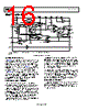
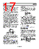
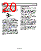
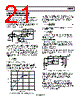
18 / 28 page  AD8232 Data Sheet Rev. A | Page 18 of 28 Figure 49. Timing Diagram for Fast Restore Switches (Time Base Not to Scale) If this saturation condition is present when both input electrodes are attached to the subject, the comparator triggers a timing circuit that automatically closes Switch S1 and Switch S2 (see Figure 49 for a timing diagram). These two switches (S1 and S2) enable two different 10 kΩ resistor paths: one between HPSENSE and IAOUT and another between SW and REFOUT. During the time Switch S1 and Switch S2 are enabled, these internal resistors appear in parallel with their corresponding external resistors forming high-pass filters. The result is that the equivalent lower resistance shifts the pole to a higher frequency, delivering a quicker settling time. Note that the fast restore settling time depends on how quickly the internal 10 kΩ resistors of the AD8232 can drain the capacitors in the high-pass circuit. Smaller capacitor values result in a shorter settling time. If, by the end of the timing, the saturation condition persists, the cycle repeats. Otherwise, the AD8232 returns to its normal operation. If either of the leads off comparator outputs is indi- cating that an electrode has been disconnected, the timing circuit is prevented from triggering because it is assumed that no valid signal is present. To disable fast restore, drive the FR pin low or tie it permanently to GND. LEADS OFF DETECTION The AD8232 includes leads off detection. It features ac and dc detection modes optimized for either two- or three-electrode configurations, respectively. DC Leads Off Detection The dc leads off detection mode is used in three-electrode con- figurations only. It works by sensing when either instrumentation amplifier input voltage is within 0.5 V from the positive rail. In this case, each input must have a pull-up resistor connected to the positive supply. During normal operation, the subject’s potential must be inside the common-mode range of the instrumentation amplifier, which is only possible if a third electrode is connected to the output of the right leg drive amplifier. Figure 50. Circuit Configuration for DC Leads Off Detection Because in dc leads off mode the AD8232 checks each input individually, it is possible to indicate which electrode is discon- nected. The AD8232 indicates which electrode is disconnected by setting the corresponding LOD− or LOD+ pin high. To use this mode, connect the AC/DC pin to ground. LEADS OFF LEADS ON S1 S2 SATURATION DETECTED NO SATURATION tS1 tS2 tRST RLD 10MΩ 10MΩ TO DRIVEN ELECTRODE IA 2 3 5 +VS |
|
Link URL |
| Cho đến nay ALLDATASHEET có giúp ích cho doanh nghiệp của bạn hay không? [ DONATE ] |
Alldatasheet là | Quảng cáo | Liên lạc với chúng tôi | Chính sách bảo mật | Liên kết đến bảng dữ liệu | Trao đổi link | Tìm kiếm theo nhà sản xuất All Rights Reserved©Alldatasheet.com |
| Russian : Alldatasheetru.com | Korean : Alldatasheet.co.kr | Spanish : Alldatasheet.es | French : Alldatasheet.fr | Italian : Alldatasheetit.com Portuguese : Alldatasheetpt.com | Polish : Alldatasheet.pl | Vietnamese : Alldatasheet.vn Indian : Alldatasheet.in | Mexican : Alldatasheet.com.mx | British : Alldatasheet.co.uk | New Zealand : Alldatasheet.co.nz |
|
Family Site : ic2ic.com |
icmetro.com |
 Vietnamese ▼
 English
 Chinese
 German
 Japanese
 Russian
 Korean
 Spanish
 French
 Italian
 Portuguese
 Polish
 Vietnamese
 Indian
 Mexican
 British
 New Zealand