|
công cụ tìm kiếm bảng dữ liệu linh kiện điện tử |
|
|
công cụ tìm kiếm bảng dữ liệu linh kiện điện tử |
|
PT6903N bảng dữ liệu(PDF) 3 Page - Texas Instruments |
|
|
|||||||||||||||||||||||||||||
PT6903N bảng dữ liệu(HTML) 3 Page - Texas Instruments |
|
|
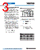
3 / 7 page  Application Notes For technical support and more information, see inside back cover or visit www.ti.com/powertrends PT6900/6910 Series Adjusting the Output Voltage of the PT6900/PT6910 Positive to Negative Converter Series The negative output voltage of the Power Trends PT6900 Series ISRs may be adjusted higher or lower than the factory trimmed pre-set voltage with the addi- tion of a single external resistor. Table 1 gives the allowable adjustment range for each model in the series as V a (min) and Va (max). Adjust Up: An increase in the output voltage is obtained by adding a resistor R2, between pin 2 (V o ad- just) and pin 8 (Remote Sense GND). Adjust Down: Add a resistor (R1), between pin 2 (V o adjust) and pin 22 (Remote Sense V o). Refer to Figure 1 and Table 2 for both the placement and value of the required resistor, either (R1) or R2 as appropriate. Notes: 1. Only a single 1% resistor is required in either the (R1) or R2 location. Do not use (R1) and R2 simultaneously. Place the resistor as close to the ISR as possible. 2. Never connect capacitors from V o adjust to either GND, V out, or the Sense pins. Any capacitance added to the V o adjust pin will affect the stability of the ISR. 3. If the sense pins are not being used, the resistors (R1) and R2 can be connected to V out and GND respectively. 4. An increase in the output voltage must be accompanied by a corresponding reduction in the maximum output current. The revised maximum output current must be reduced to the equivalent of 12Watts. i.e. Iout (max) = 12 Adc, Va where V a is the adjusted output voltage. Figure 1 The respective values of (R1) [adjust down], and R2 [ad- just up], can also be calculated using the following formulas. (R1) = 24.9 (Va – Vr) – Rs kΩ (Vo – Va) R2 = 24.9 Vr – Rs k Ω (Va – Vo) Where: Vo = Original output voltage Va = Adjusted output voltage Vr = Reference voltage in Table 1 Rs = The resistance given in Table 1 Table1 PT6900/PT6910 ADJUSTMENT RANGE AND FORMULA PARAMETERS Series Pt # 5.0V Bus PT6903/13 PT6901/11 PT6902/12 3.3V Bus PT6904/14 PT6905/15 Vo (nom) -1.5V -2.0V -5.2V Va (min) -1.2V -1.4V -2.7V Va (max) -3.4V -4.5V -6.5V Vr -1.0V -1.0V -0.92V Rs (k Ω Ω Ω Ω Ω) 12.7 10.0 17.4 C in + C out R2 (Up) (R1) (Down) COM COM Vout(-) +Vin PT6900 16 - 21 2 9 - 15 3 - 7 +Vin -Vo GND Vo(adj) Vo(sense) 22 8 GND(sense) L O A D |
|
|
Link URL |
| Cho đến nay ALLDATASHEET có giúp ích cho doanh nghiệp của bạn hay không? [ DONATE ] |
Alldatasheet là | Quảng cáo | Liên lạc với chúng tôi | Chính sách bảo mật | Liên kết đến bảng dữ liệu | Trao đổi link | Tìm kiếm theo nhà sản xuất All Rights Reserved©Alldatasheet.com |
| Russian : Alldatasheetru.com | Korean : Alldatasheet.co.kr | Spanish : Alldatasheet.es | French : Alldatasheet.fr | Italian : Alldatasheetit.com Portuguese : Alldatasheetpt.com | Polish : Alldatasheet.pl | Vietnamese : Alldatasheet.vn Indian : Alldatasheet.in | Mexican : Alldatasheet.com.mx | British : Alldatasheet.co.uk | New Zealand : Alldatasheet.co.nz |
|
Family Site : ic2ic.com |
icmetro.com |
 Vietnamese ▼
 English
 Chinese
 German
 Japanese
 Russian
 Korean
 Spanish
 French
 Italian
 Portuguese
 Polish
 Vietnamese
 Indian
 Mexican
 British
 New Zealand