|
công cụ tìm kiếm bảng dữ liệu linh kiện điện tử |
|
|
công cụ tìm kiếm bảng dữ liệu linh kiện điện tử |
|
INMP411ACEZ-R7 bảng dữ liệu(PDF) 10 Page - TDK Electronics |
|
|
|||||||||||||||||||||||||||||
INMP411ACEZ-R7 bảng dữ liệu(HTML) 10 Page - TDK Electronics |
|
|
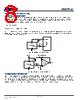
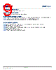
10 / 14 page  INMP411 PCB DESIGN AND LAND PATTERN LAYOUT The recommended PCB land pattern for the INMP411 should be laid out to a 1:1 ratio to the solder pads on the microphone package, as shown in Figure 8. Take care to avoid applying solder paste to the sound hole in the PCB. A suggested solder paste stencil pattern layout is shown in Figure 9. The diameter of the sound hole in the PCB should be larger than the diameter of the sound port of the microphone. A minimum diameter of 0.5 mm is recommended. Figure 11. PCB Land Pattern Layout Dimensions shown in millimeters Figure 12. Suggested Solder Paste Stencil Pattern Layout Dimensions shown in millimeters 2.62 ø1.10 ø1.68 ø0.70 (2×) ø0.90 (3×) 2.40 1.20 2.54 0.79 1.27 1.27mm 1.2mm 2.54mm 2.62mm 3.41mm 2.4mm 0.85mm DIA. (3×) 1.8mm/1.3mm DIA. 0.2032 CUT WIDTH (4×) 0.649mm DIA. (2×) Page 10 of 14 Document Number: DS-INMP411-00 Revision: 1.0. |
|
|
Link URL |
| Cho đến nay ALLDATASHEET có giúp ích cho doanh nghiệp của bạn hay không? [ DONATE ] |
Alldatasheet là | Quảng cáo | Liên lạc với chúng tôi | Chính sách bảo mật | Liên kết đến bảng dữ liệu | Trao đổi link | Tìm kiếm theo nhà sản xuất All Rights Reserved©Alldatasheet.com |
| Russian : Alldatasheetru.com | Korean : Alldatasheet.co.kr | Spanish : Alldatasheet.es | French : Alldatasheet.fr | Italian : Alldatasheetit.com Portuguese : Alldatasheetpt.com | Polish : Alldatasheet.pl | Vietnamese : Alldatasheet.vn Indian : Alldatasheet.in | Mexican : Alldatasheet.com.mx | British : Alldatasheet.co.uk | New Zealand : Alldatasheet.co.nz |
|
Family Site : ic2ic.com |
icmetro.com |
 Vietnamese ▼
 English
 Chinese
 German
 Japanese
 Russian
 Korean
 Spanish
 French
 Italian
 Portuguese
 Polish
 Vietnamese
 Indian
 Mexican
 British
 New Zealand