|
công cụ tìm kiếm bảng dữ liệu linh kiện điện tử |
|
|
công cụ tìm kiếm bảng dữ liệu linh kiện điện tử |
|
AD8232ACPZ-R7 bảng dữ liệu(PDF) 7 Page - Analog Devices |
|
|
|||||||||||||||||||||||||||||
AD8232ACPZ-R7 bảng dữ liệu(HTML) 7 Page - Analog Devices |
|
|
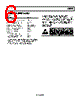
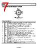
7 / 29 page  AD8232 Data Sheet Rev. B | Page 6 of 28 PIN CONFIGURATION AND FUNCTION DESCRIPTIONS Figure 2. Pin Configuration Table 3. Pin Function Descriptions Pin No. Mnemonic Description 1 HPDRIVE High-Pass Driver Output. Connect HPDRIVE to the capacitor in the first high-pass filter. The AD8232 drives this pin to keep HPSENSE at the same level as the reference voltage. 2 +IN Instrumentation Amplifier Positive Input. +IN is typically connected to the left arm (LA) electrode. 3 −IN Instrumentation Amplifier Negative Input. −IN is typically connected to the right arm (RA) electrode. 4 RLDFB Right Leg Drive Feedback Input. RLDFB is the feedback terminal for the right leg drive circuit. 5 RLD Right Leg Drive Output. Connect the driven electrode (typically, right leg) to the RLD pin. 6 SW Fast Restore Switch Terminal. Connect this terminal to the output of the second high-pass filter. 7 OPAMP+ Operational Amplifier Noninverting Input. 8 REFOUT Reference Buffer Output. The instrumentation amplifier output is referenced to this potential. Use REFOUT as a virtual ground for any point in the circuit that needs a signal reference. 9 OPAMP− Operational Amplifier Inverting Input. 10 OUT Operational Amplifier Output. The fully conditioned heart rate signal is present at this output. OUT can be connected to the input of an ADC. 11 LOD− Leads Off Comparator Output. In dc leads off detection mode, LOD− is high when the electrode to −IN is disconnected, and it is low when connected. In ac leads off detection mode, LOD− is always low. 12 LOD+ Leads Off Comparator Output. In dc leads off detection mode, LOD+ is high when the +IN electrode is disconnected, and it is low when connected. In ac leads off detection mode, LOD+ is high when either the −IN or +IN electrode is disconnected, and it is low when both electrodes are connected. 13 SDN Shutdown Control Input. Drive SDN low to enter the low power shutdown mode. 14 AC/DC Leads Off Mode Control Input. Drive the AC/DC pin low for dc leads off mode. Drive the AC/DC pin high for ac leads off mode. 15 FR Fast Restore Control Input. Drive FR high to enable fast recovery mode; otherwise, drive it low. 16 GND Power Supply Ground. 17 +VS Power Supply Terminal. 18 REFIN Reference Buffer Input. Use REFIN, a high impedance input terminal, to set the level of the reference buffer. 19 IAOUT Instrumentation Amplifier Output Terminal. 20 HPSENSE High-Pass Sense Input for Instrumentation Amplifier. Connect HPSENSE to the junction of R and C that sets the corner frequency of the dc blocking circuit. EP Exposed Pad. Connect the exposed pad to GND or leave it unconnected. 14 13 12 1 3 4 AC/DC 15 FR SDN LOD+ 11 LOD– HPDRIVE –IN 2 +IN RLDFB 5 RLD AD8232 TOP VIEW (Not to Scale) NOTES 1. CONNECT THE EXPOSED PAD TO GND OR LEAVE UNCONNECTED. |
|
Link URL |
| Cho đến nay ALLDATASHEET có giúp ích cho doanh nghiệp của bạn hay không? [ DONATE ] |
Alldatasheet là | Quảng cáo | Liên lạc với chúng tôi | Chính sách bảo mật | Liên kết đến bảng dữ liệu | Trao đổi link | Tìm kiếm theo nhà sản xuất All Rights Reserved©Alldatasheet.com |
| Russian : Alldatasheetru.com | Korean : Alldatasheet.co.kr | Spanish : Alldatasheet.es | French : Alldatasheet.fr | Italian : Alldatasheetit.com Portuguese : Alldatasheetpt.com | Polish : Alldatasheet.pl | Vietnamese : Alldatasheet.vn Indian : Alldatasheet.in | Mexican : Alldatasheet.com.mx | British : Alldatasheet.co.uk | New Zealand : Alldatasheet.co.nz |
|
Family Site : ic2ic.com |
icmetro.com |
 Vietnamese ▼
 English
 Chinese
 German
 Japanese
 Russian
 Korean
 Spanish
 French
 Italian
 Portuguese
 Polish
 Vietnamese
 Indian
 Mexican
 British
 New Zealand