 |
công cụ tìm kiếm bảng dữ liệu linh kiện điện tử |
|
|
công cụ tìm kiếm bảng dữ liệu linh kiện điện tử |
|
The question interval is too short.
Please try again in a few seconds.

Hello, Please ask a question about MXHV9910 Datasheet
# Example questions:
➢ What is the primary purpose of the current sense blanking feature in the mxhv9910?
➢ What is the relationship between the external resistor connected to the rt pin and the switching frequency (fs) of the mxhv9910?
➢ Explain how the mxhv9910 enables dimming of leds and list the two methods described in the text.
| Part No. | MXHV9910 |
| Manufacturer | CLARE |
| Size | 604 Kbytes |
| Pages | 11 pages |
| Description | Off-Line, High Brightness LED Driver |


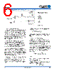

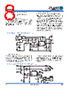


1. Overview
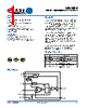
️· What it is: A constant frequency, off-line LED driver IC.
️· Purpose: Designed to drive multiple LEDs in series or parallel, often used in flat panel backlights, signage, and decorative lighting.
️· Topology: Buck converter.
️· Key Advantages:
- High Efficiency
- Minimal External Components
- Integrated voltage regulator simplifies startup and bias power
- No external RC filtering needed for current sense blanking
- Flexible dimming options (DC control via LD pin or PWM via PWMD pin)
2. Functionality
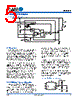
️· Enable/Disable: PWMD pin controls the gate driver. PWMD tied to VDD = Enabled; PWMD tied to GND = Disabled (shutdown mode).
️· LED Driver: Works by switching the power MOSFET on and off, controlling the inductor current.
️· Current Sense: External resistor (R_SENSE) sets the peak LED current.
️· Dimming:
- LD Pin: Can override the default current sense threshold (V_CS(high)) to lower the peak current (soft start can be implemented here)
- PWMD Pin: Applying a low-frequency PWM signal (typically 500Hz) to the PWMD pin enables PWM dimming.
️· Voltage Regulator: Internal regulator provides a regulated output (typically 7.8V) from an input voltage range of 12V to 450V. This can be bypassed with an external supply for more efficient isolated applications.
️· Oscillator: External resistor (R_T) determines the switching frequency.
️· Current Sense Blanking: Internal blanking circuit prevents premature termination of the gate drive signal.
️· Soft Start: Achieved by slowly ramping up the voltage on the LD pin.
3. Design Considerations
️· Current Sense Resistor (R_SENSE):
- Critical for setting peak LED current.
- Calculated based on desired LED current, ripple current, and the internal current sense threshold.
- Power dissipation must be considered – select a resistor with adequate power rating.
️· Inductor:
- Size is determined by LED ripple current, maximum on-time, and the LED string voltage.
- Maximum duty cycle should be kept below 50%.
️· Switching Frequency: Controlled by R_T resistor. Range is typically 30kHz to 120kHz.
️· Input Capacitor: Low ESR capacitor is required at VDD to minimize switching noise.
️· PWM Frequency: The recommended PWM dimming frequency is 500Hz.
️· Soft Start Implementation: Implement soft start by slowly ramping the voltage applied to the LD pin.
4. Key Equations
️· Enable/Disable (Duty Cycle):
`D_max = V_LEDstring / (V_in - V_LEDstring)`
️· Maximum ON-Time:
`t_ONmax = D_max / f_s`
️· Minimum Inductance:
`L_min = (V_in - V_LEDstring) * t_ONmax / I_LED`
️· Current Sense Resistor:
`R_sense = [1 + (0.5 * V_ripple)] / I_LED`
️· Input Current (approximate):
`I_in ≈ 0.6mA + (Q_gate * f_s)` (where Q_gate is total gate charge and f_s is switching frequency)
️· Switching Frequency (oscillator): (Refer to Figure 4 in the datasheet)
Important Notes:
️· Datasheets are essential: This summary is a guide. Always refer to the full datasheet for complete specifications, detailed diagrams, application examples, and safety precautions.
️· Simulation: Simulations are highly recommended before building a physical circuit.
️· Component Selection: Carefully select components with appropriate voltage, current, and power ratings.
1. Overview
️· What it is: A constant frequency, off-line LED driver IC.
️· Purpose: Designed to drive multiple LEDs in series or parallel, often used in flat panel backlights, signage, and decorative lighting.
️· Topology: Buck converter.
️· Key Advantages:
- High Efficiency
- Minimal External Components
- Integrated voltage regulator simplifies startup and bias power
- No external RC filtering needed for current sense blanking
- Flexible dimming options (DC control via LD pin or PWM via PWMD pin)
2. Functionality
️· Enable/Disable: PWMD pin controls the gate driver. PWMD tied to VDD = Enabled; PWMD tied to GND = Disabled (shutdown mode).
️· LED Driver: Works by switching the power MOSFET on and off, controlling the inductor current.
️· Current Sense: External resistor (R_SENSE) sets the peak LED current.
️· Dimming:
- LD Pin: Can override the default current sense threshold (V_CS(high)) to lower the peak current (soft start can be implemented here)
- PWMD Pin: Applying a low-frequency PWM signal (typically 500Hz) to the PWMD pin enables PWM dimming.
️· Voltage Regulator: Internal regulator provides a regulated output (typically 7.8V) from an input voltage range of 12V to 450V. This can be bypassed with an external supply for more efficient isolated applications.
️· Oscillator: External resistor (R_T) determines the switching frequency.
️· Current Sense Blanking: Internal blanking circuit prevents premature termination of the gate drive signal.
️· Soft Start: Achieved by slowly ramping up the voltage on the LD pin.
3. Design Considerations
️· Current Sense Resistor (R_SENSE):
- Critical for setting peak LED current.
- Calculated based on desired LED current, ripple current, and the internal current sense threshold.
- Power dissipation must be considered – select a resistor with adequate power rating.
️· Inductor:
- Size is determined by LED ripple current, maximum on-time, and the LED string voltage.
- Maximum duty cycle should be kept below 50%.
️· Switching Frequency: Controlled by R_T resistor. Range is typically 30kHz to 120kHz.
️· Input Capacitor: Low ESR capacitor is required at VDD to minimize switching noise.
️· PWM Frequency: The recommended PWM dimming frequency is 500Hz.
️· Soft Start Implementation: Implement soft start by slowly ramping the voltage applied to the LD pin.
4. Key Equations
️· Enable/Disable (Duty Cycle):
`D_max = V_LEDstring / (V_in - V_LEDstring)`
️· Maximum ON-Time:
`t_ONmax = D_max / f_s`
️· Minimum Inductance:
`L_min = (V_in - V_LEDstring) * t_ONmax / I_LED`
️· Current Sense Resistor:
`R_sense = [1 + (0.5 * V_ripple)] / I_LED`
️· Input Current (approximate):
`I_in ≈ 0.6mA + (Q_gate * f_s)` (where Q_gate is total gate charge and f_s is switching frequency)
️· Switching Frequency (oscillator): (Refer to Figure 4 in the datasheet)
Important Notes:
️· Datasheets are essential: This summary is a guide. Always refer to the full datasheet for complete specifications, detailed diagrams, application examples, and safety precautions.
️· Simulation: Simulations are highly recommended before building a physical circuit.
️· Component Selection: Carefully select components with appropriate voltage, current, and power ratings.
| Part No. | MXHV9910 |
| Manufacturer | CLARE |
| Size | 604 Kbytes |
| Pages | 11 pages |
| Description | Off-Line, High Brightness LED Driver |
| Cho đến nay ALLDATASHEET có giúp ích cho doanh nghiệp của bạn hay không? [ DONATE ] |
Alldatasheet là | Quảng cáo | Liên lạc với chúng tôi | Chính sách bảo mật | Liên kết đến bảng dữ liệu | Trao đổi link | Tìm kiếm theo nhà sản xuất All Rights Reserved©Alldatasheet.com |
| Russian : Alldatasheetru.com | Korean : Alldatasheet.co.kr | Spanish : Alldatasheet.es | French : Alldatasheet.fr | Italian : Alldatasheetit.com Portuguese : Alldatasheetpt.com | Polish : Alldatasheet.pl | Vietnamese : Alldatasheet.vn Indian : Alldatasheet.in | Mexican : Alldatasheet.com.mx | British : Alldatasheet.co.uk | New Zealand : Alldatasheet.co.nz |
|
Family Site : ic2ic.com |
icmetro.com |
 Vietnamese ▼
  English
 Chinese
 German
 Japanese
 Russian
 Korean
 Spanish
 French
 Italian
 Portuguese
 Polish
 Indian
 Mexican
 British
 New Zealand