 |
công cụ tìm kiếm bảng dữ liệu linh kiện điện tử |
|
|
công cụ tìm kiếm bảng dữ liệu linh kiện điện tử |
|
The question interval is too short.
Please try again in a few seconds.

Hello, Please ask a question about AMS1085CD Datasheet
# Example questions:
➢ What is the typical output capacitor value recommended for ensuring stability in the ams1085 regulator?
➢ What is a key difference between the thermal resistance specifications of the ams1085 series compared to older regulators?
➢ The document mentions a potential issue with 'double intersection' in the load line. what can cause this issue and how can it be resolved?
| Part No. | AMS1085CD |
| Manufacturer | ADMOS |
| Size | 85 Kbytes |
| Pages | 9 pages |
| Description | 3A LOW DROPOUT VOLTAGE REGULATOR |

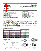
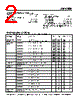
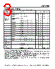
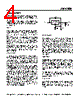
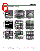
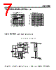

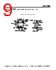

Okay, here's a summary of the provided AMS1085 datasheet extract, broken down into key sections and points. I've aimed for clarity and conciseness.
1. Overview & General Information
️· Device: AMS1085 Adjustable/Fixed Voltage Regulator
️· Family: Part of the AMS1085 series – designed as an improvement over older regulators with lower dropout voltage, tighter tolerance, and better stability.
️· Pin Compatibility: Pin-compatible with older, adjustable three-terminal regulators.
️· Features: Short-circuit protection, thermal shutdown.
2. Electrical Characteristics (Key Points)
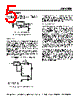
️· Adjustable Output Voltage: Defined by external resistors (R1 and R2) - *V OUT = V REF (1 + R2/R1) + I ADJ * R2*.
️· Reference Voltage (V REF): 1.25V
️· Minimum Load Current: 10mA (required for regulation)
3. Application Hints & Design Considerations
️· Stability: Requires an output capacitor (150µF electrolytic or 22µF tantalum) for stability. Larger capacitors improve transient response.
️· Ripple Rejection: Optimal ripple rejection requires bypassing the adjustment pin.
️· Protection Diodes: Not typically required (internal limiting resistors). However, a diode from input to output *is* recommended when using a crowbar circuit at the input and *may* be needed with high-value output capacitance and an instant grounding of the input pin.
️· Overload Recovery: In some cases, the power supply may need to be cycled (turned off and back on) to recover from an overload condition.
️· Load Regulation: Best load regulation is achieved by connecting R1 to the device case and R2 to the load, minimizing parasitic line resistance.
️· Thermal Considerations:
- Junction-to-case thermal resistance is critical for heat dissipation.
- Use thermal compound for optimal case-to-heat sink contact.
- Separate thermal resistance specifications are provided for the Control Section and the Power Transistor.
Key Formulas/Equations
️· Output Voltage Calculation: V OUT = V REF (1 + R2/R1) + I ADJ * R2
️· Ripple Rejection optimization: R1 value should be greater than the impedance of the adjust pin capacitor.
Let me know if you'd like me to elaborate on any of these points or focus on a specific aspect of the AMS1085!
1. Overview & General Information
️· Device: AMS1085 Adjustable/Fixed Voltage Regulator
️· Family: Part of the AMS1085 series – designed as an improvement over older regulators with lower dropout voltage, tighter tolerance, and better stability.
️· Pin Compatibility: Pin-compatible with older, adjustable three-terminal regulators.
️· Features: Short-circuit protection, thermal shutdown.
2. Electrical Characteristics (Key Points)
️· Adjustable Output Voltage: Defined by external resistors (R1 and R2) - *V OUT = V REF (1 + R2/R1) + I ADJ * R2*.
️· Reference Voltage (V REF): 1.25V
️· Minimum Load Current: 10mA (required for regulation)
3. Application Hints & Design Considerations
️· Stability: Requires an output capacitor (150µF electrolytic or 22µF tantalum) for stability. Larger capacitors improve transient response.
️· Ripple Rejection: Optimal ripple rejection requires bypassing the adjustment pin.
️· Protection Diodes: Not typically required (internal limiting resistors). However, a diode from input to output *is* recommended when using a crowbar circuit at the input and *may* be needed with high-value output capacitance and an instant grounding of the input pin.
️· Overload Recovery: In some cases, the power supply may need to be cycled (turned off and back on) to recover from an overload condition.
️· Load Regulation: Best load regulation is achieved by connecting R1 to the device case and R2 to the load, minimizing parasitic line resistance.
️· Thermal Considerations:
- Junction-to-case thermal resistance is critical for heat dissipation.
- Use thermal compound for optimal case-to-heat sink contact.
- Separate thermal resistance specifications are provided for the Control Section and the Power Transistor.
Key Formulas/Equations
️· Output Voltage Calculation: V OUT = V REF (1 + R2/R1) + I ADJ * R2
️· Ripple Rejection optimization: R1 value should be greater than the impedance of the adjust pin capacitor.
| Part No. | AMS1085CD |
| Manufacturer | ADMOS |
| Size | 85 Kbytes |
| Pages | 9 pages |
| Description | 3A LOW DROPOUT VOLTAGE REGULATOR |
| Cho đến nay ALLDATASHEET có giúp ích cho doanh nghiệp của bạn hay không? [ DONATE ] |
Alldatasheet là | Quảng cáo | Liên lạc với chúng tôi | Chính sách bảo mật | Liên kết đến bảng dữ liệu | Trao đổi link | Tìm kiếm theo nhà sản xuất All Rights Reserved©Alldatasheet.com |
| Russian : Alldatasheetru.com | Korean : Alldatasheet.co.kr | Spanish : Alldatasheet.es | French : Alldatasheet.fr | Italian : Alldatasheetit.com Portuguese : Alldatasheetpt.com | Polish : Alldatasheet.pl | Vietnamese : Alldatasheet.vn Indian : Alldatasheet.in | Mexican : Alldatasheet.com.mx | British : Alldatasheet.co.uk | New Zealand : Alldatasheet.co.nz |
|
Family Site : ic2ic.com |
icmetro.com |
 Vietnamese ▼
  English
 Chinese
 German
 Japanese
 Russian
 Korean
 Spanish
 French
 Italian
 Portuguese
 Polish
 Indian
 Mexican
 British
 New Zealand