 |
công cụ tìm kiếm bảng dữ liệu linh kiện điện tử |
|
|
công cụ tìm kiếm bảng dữ liệu linh kiện điện tử |
|
The question interval is too short.
Please try again in a few seconds.

Hello, Please ask a question about ICS950202 Datasheet
# Example questions:
➢ Describe the sequence a host controller would use to read the value of 'byte 0' from the ics slave device.
➢ What is the maximum discrete cap load allowed when the supply voltage is 465v, and all static inputs are either vdd or gnd?
➢ Explain the purpose of the 'multisel0' and 'boardtarget' settings within the 'host swing select functions' table, and how they relate to the output current.
| Part No. | ICS950202 |
| Manufacturer | RENESAS |
| Size | 416 Kbytes |
| Pages | 21 pages |
| Description | Programmable Timing Control HubTM for P4TM |

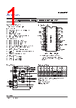


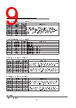
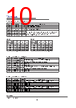
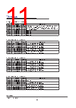



1. Overall Structure & Purpose
️· IC Communication & Control: The document details how a "Controller" (host, usually a microcontroller or computer) communicates with an "ICS" (the IC itself - likely a slave device) using I²C serial communication.
️· I²C Protocol: The focus is on the I²C communication protocol (a two-wire serial communication protocol) detailing the write and read sequences, acknowledgement (ACK) signals, and how data is transferred.
️· Data Organization: The IC has registers that can be written to and read from. The documentation outlines how to access and control the IC through these registers.
️· Tables & Diagrams: Extensive use of tables to describe the communication sequence, register organization, and specific signal timings.
2. Key Sections & Content Breakdown
️· "Maximum Allowed Current" (Page 1): Provides operational limits. Important for power supply design and ensuring the IC operates within safe parameters. It shows the max consumption and discrete load cap values.
️· "Host Swing Select Functions" (Page 1): This describes how to configure the output current drive strength (how much current the IC can provide on its output pins) based on settings like `MULTISEL0` and `BoardTarget`. This likely impacts signal integrity and the ability to drive different load impedances.
️· "General I²C Serial Interface Information" (Pages 2-3):
- Write Sequence: The "How to Write" section explains the steps required to write data to the IC's registers. It details the start bit, slave address, data byte count, data transmission, and stop bit.
- Read Sequence: The "How to Read" section details the sequence for reading data from the IC's registers. It includes a repeat start condition.
- Table - Index Block Read/Write Operations: Visualizes the data flow between the controller and ICS, showing the signals exchanged at each step.
️· "Byte 0: Functionality and frequency select register (Default=0)" (Page 4): Starts to describe the structure of the IC's registers. It indicates this is the first register (Byte 0) and its purpose is to select functionality and frequency. The "SUMMARY" indicates there is further detailed information about this register that is not included in the excerpt.
3. Key Concepts & Terminology
️· I²C (Inter-Integrated Circuit): A serial communication protocol.
️· Controller/Host: The device initiating the communication (usually a microcontroller).
️· ICS (Integrated Circuit Slave): The device responding to the controller.
️· Slave Address: A unique identifier for the ICS on the I²C bus.
️· Start Bit: A signal that initiates I²C communication.
️· Stop Bit: A signal that terminates I²C communication.
️· ACK (Acknowledgement): A signal from the ICS to the controller indicating it has received data.
️· Register: A storage location within the ICS.
️· Byte: A unit of data (8 bits).
️· Repeat Start: a special condition in I²C where the master (controller) issues a start condition without issuing a stop condition.
4. Potential Uses
This datasheet excerpt would be used by:
️· Hardware Engineers: Designing circuits that incorporate this IC.
️· Software Developers: Writing firmware or software to communicate with and control the IC.
️· System Integrators: Integrating the IC into a larger system.
1. Overall Structure & Purpose
️· IC Communication & Control: The document details how a "Controller" (host, usually a microcontroller or computer) communicates with an "ICS" (the IC itself - likely a slave device) using I²C serial communication.
️· I²C Protocol: The focus is on the I²C communication protocol (a two-wire serial communication protocol) detailing the write and read sequences, acknowledgement (ACK) signals, and how data is transferred.
️· Data Organization: The IC has registers that can be written to and read from. The documentation outlines how to access and control the IC through these registers.
️· Tables & Diagrams: Extensive use of tables to describe the communication sequence, register organization, and specific signal timings.
2. Key Sections & Content Breakdown
️· "Maximum Allowed Current" (Page 1): Provides operational limits. Important for power supply design and ensuring the IC operates within safe parameters. It shows the max consumption and discrete load cap values.
️· "Host Swing Select Functions" (Page 1): This describes how to configure the output current drive strength (how much current the IC can provide on its output pins) based on settings like `MULTISEL0` and `BoardTarget`. This likely impacts signal integrity and the ability to drive different load impedances.
️· "General I²C Serial Interface Information" (Pages 2-3):
- Write Sequence: The "How to Write" section explains the steps required to write data to the IC's registers. It details the start bit, slave address, data byte count, data transmission, and stop bit.
- Read Sequence: The "How to Read" section details the sequence for reading data from the IC's registers. It includes a repeat start condition.
- Table - Index Block Read/Write Operations: Visualizes the data flow between the controller and ICS, showing the signals exchanged at each step.
️· "Byte 0: Functionality and frequency select register (Default=0)" (Page 4): Starts to describe the structure of the IC's registers. It indicates this is the first register (Byte 0) and its purpose is to select functionality and frequency. The "SUMMARY" indicates there is further detailed information about this register that is not included in the excerpt.
3. Key Concepts & Terminology
️· I²C (Inter-Integrated Circuit): A serial communication protocol.
️· Controller/Host: The device initiating the communication (usually a microcontroller).
️· ICS (Integrated Circuit Slave): The device responding to the controller.
️· Slave Address: A unique identifier for the ICS on the I²C bus.
️· Start Bit: A signal that initiates I²C communication.
️· Stop Bit: A signal that terminates I²C communication.
️· ACK (Acknowledgement): A signal from the ICS to the controller indicating it has received data.
️· Register: A storage location within the ICS.
️· Byte: A unit of data (8 bits).
️· Repeat Start: a special condition in I²C where the master (controller) issues a start condition without issuing a stop condition.
4. Potential Uses
This datasheet excerpt would be used by:
️· Hardware Engineers: Designing circuits that incorporate this IC.
️· Software Developers: Writing firmware or software to communicate with and control the IC.
️· System Integrators: Integrating the IC into a larger system.
| Part No. | ICS950202 |
| Manufacturer | RENESAS |
| Size | 416 Kbytes |
| Pages | 21 pages |
| Description | Programmable Timing Control HubTM for P4TM |
| Cho đến nay ALLDATASHEET có giúp ích cho doanh nghiệp của bạn hay không? [ DONATE ] |
Alldatasheet là | Quảng cáo | Liên lạc với chúng tôi | Chính sách bảo mật | Liên kết đến bảng dữ liệu | Trao đổi link | Tìm kiếm theo nhà sản xuất All Rights Reserved©Alldatasheet.com |
| Russian : Alldatasheetru.com | Korean : Alldatasheet.co.kr | Spanish : Alldatasheet.es | French : Alldatasheet.fr | Italian : Alldatasheetit.com Portuguese : Alldatasheetpt.com | Polish : Alldatasheet.pl | Vietnamese : Alldatasheet.vn Indian : Alldatasheet.in | Mexican : Alldatasheet.com.mx | British : Alldatasheet.co.uk | New Zealand : Alldatasheet.co.nz |
|
Family Site : ic2ic.com |
icmetro.com |
 Vietnamese ▼
  English
 Chinese
 German
 Japanese
 Russian
 Korean
 Spanish
 French
 Italian
 Portuguese
 Polish
 Indian
 Mexican
 British
 New Zealand